-
Finally the drawings for the CEB Press Version IV are released.
Its one of the oldest OSE developments, and to my knowledge a working one.Looking at the drawings I find a lot of issues to discuss. OSE with its goals for industrial efficiency should be up to industrial efficiency also in its designs and documentation, the technical drawings.
Some poor examples now:
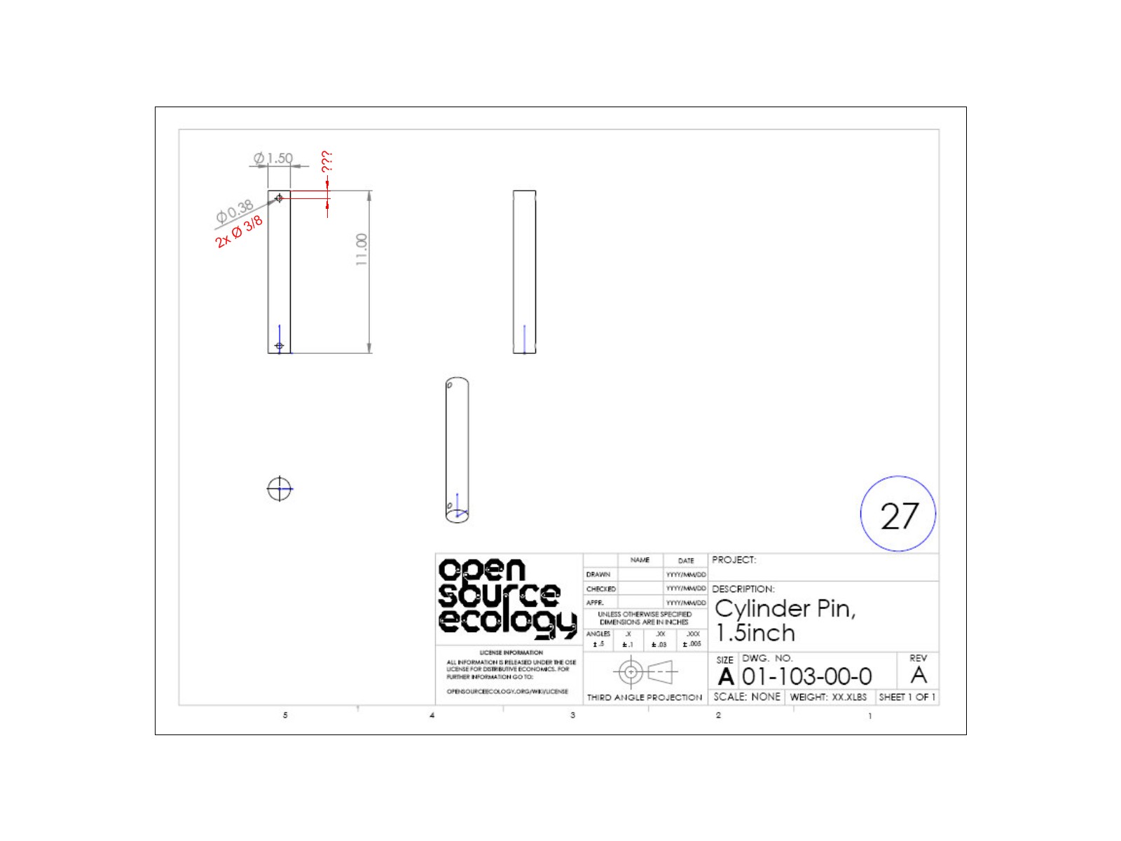
Page 4: A pin - a very simple basic part, nearly not worth doing a drawing.
 Attachments
4Fehler.JPG 107K -
7 Comments sorted by
-
Lets see page 37. An angle
Its confusing to omitt hidden lines. The dimensioning could be improved, a centerline inserted.
The hole through the inner radius of that angle looks like a design error. You can't install a nut there, on a curved surfaceAttachments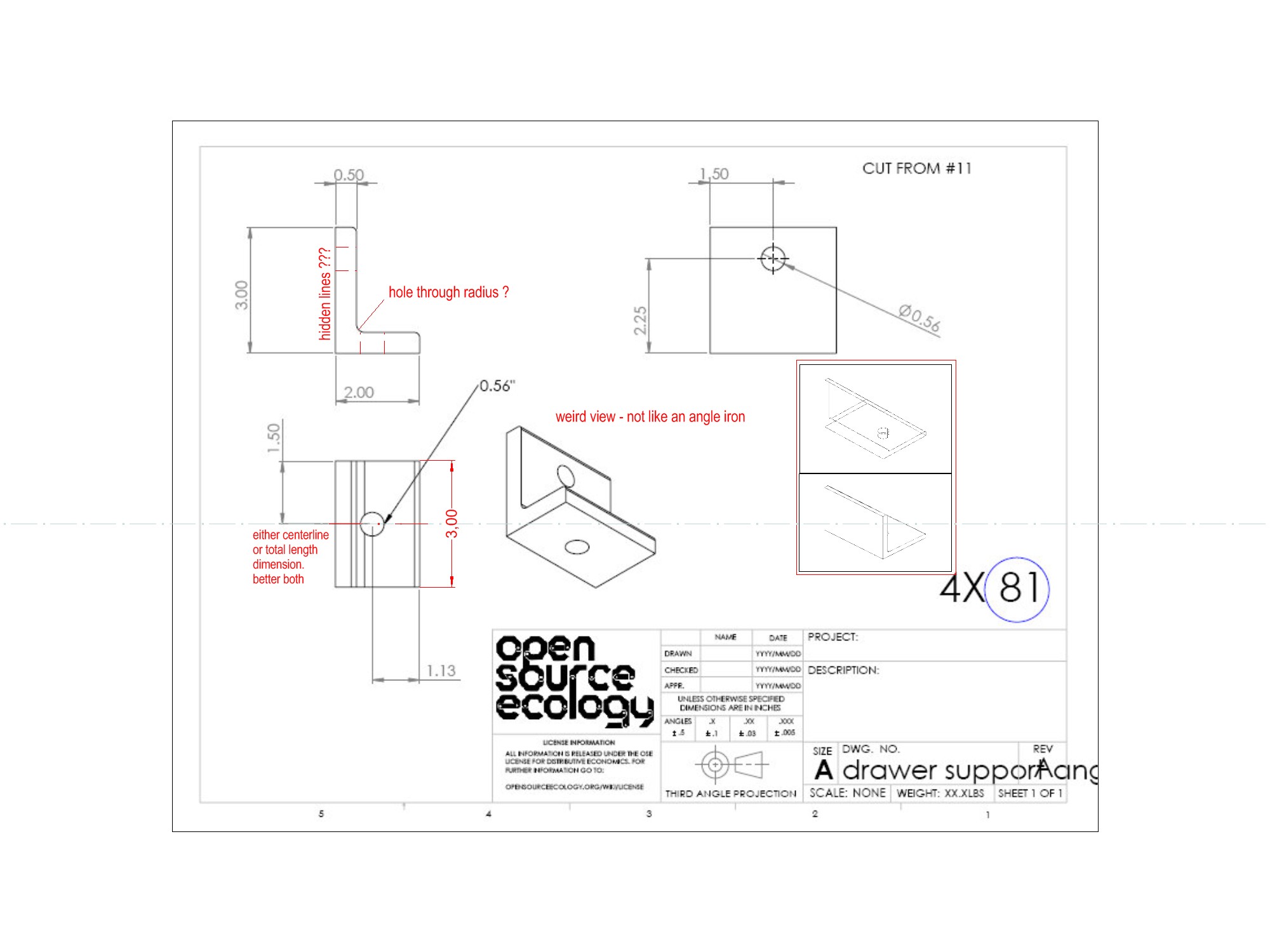
37Fehler.jpg 205K -
Lets look at a threaded rod, shown on page 24.
How, threaded???
I don't see any thread. No symbol for a thread drawn. No dimensions for a thread. The round part has a dimension of Ø3/4" - that's not thread.
Its also questionable if it's necessary to make a drawing for a standard threaded rod available in any hardware store. And if the thread isn't standard, it definitely needs to be clearly specified in the drawing.
Attachments
24Fehler.jpg 134K -
See a top view of a sheet steel part on page 43
It's just ugly to place the dimensions this way.
Worse, its a mistake to use such a corner as base for dimensions, they always have a radius from cutting. You cannot do proper layout lines from this corner, nor can a machinist with an DRO/CNC equipped machine exactly indicate his display at that corner.For manual cutting I would also dimension the angles in brackets.
Attachments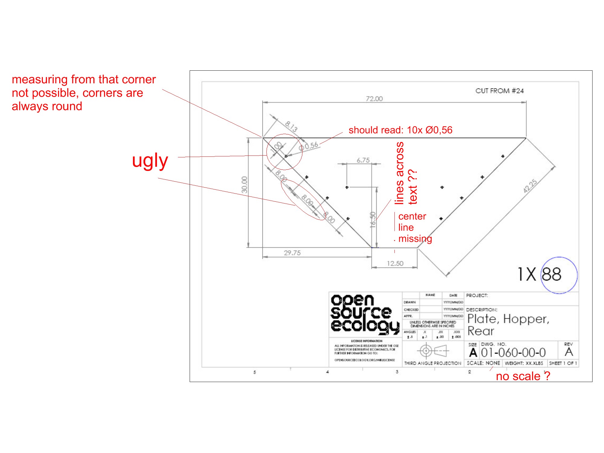
43Fehler.jpg 228K -
Similar part with similar problems on page 42
Here one dimension is misleading, and 2 others are missing completely.....
IMO it would be helpful to install for OSE to implement some quality control for drawings.
In industry most drawings are made by highly skilled professionals who make drawings all day long. Nevertheless its standard in most companies that every drawing is checked for errors by a second engineer or technician before it is released for production.Attachments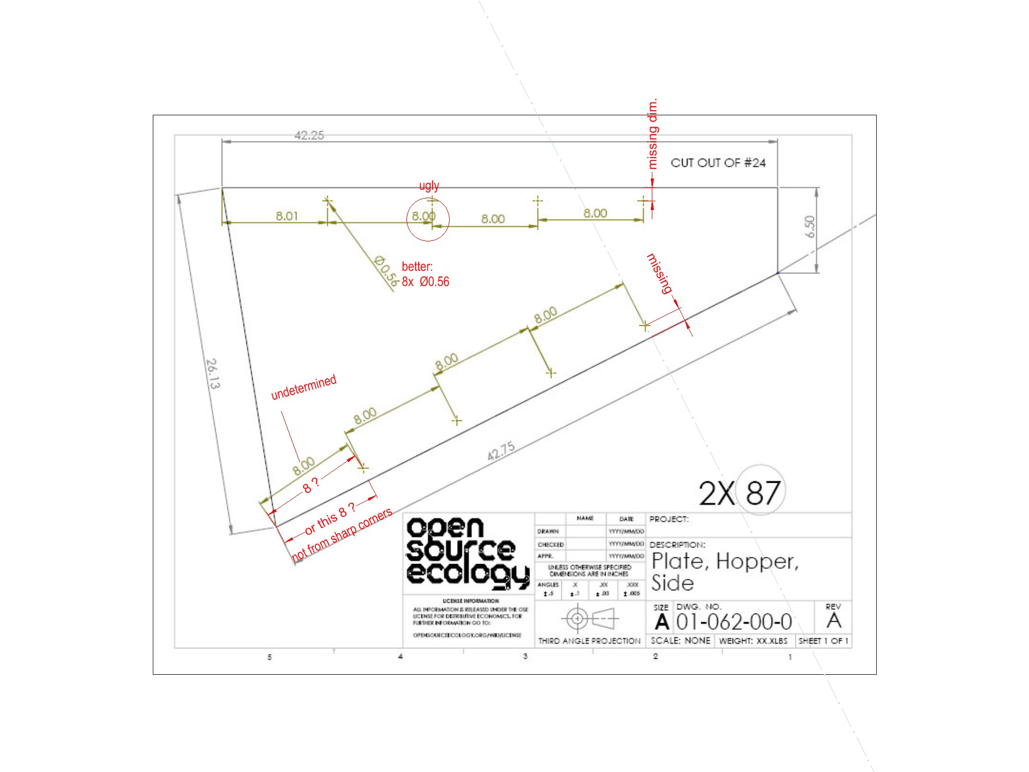
42Fehler.jpg 207K -
I started drafting when lead on vellum and slide rules where the norm. A considerable amount of work was needed to create drawings, so the quality of the work was taken seriously. Also, vendors and lawyers could try to take advantage of any flaw or ambiguity when a dispute came up. On the other hand, the drafter created these drawings from rough sketches, verbal instructions and hand waving. One might consider these CEB drawings as sketches, and as Bastelmike mentions, it would be better to have a review system to develop and review these before they can be presented as official.
Maybe for the short term, a link could be added here:
http://opensourceecology.org/wiki/Civilization_Starter_Kit_DVD_v0.01#CEB_Press
such as "CEB Drawings, Preliminary", then move the drawings over to a link with higher status as they are developed. Unfortunately, the drawings aren't even signed, so one would not know where to go if one where inclined to help.
If anyone from the development team reads this, please reply so that we at the wiki know there is some sort of connection between the wiki and the inner circle.
--
Kirk Wallace
http://www.wallacecompany.com/machine_shop/
http://www.wallacecompany.com/E45/index.html
California, USA
-
Yeah, you just cannot make perfect fab drawings from a virtual model straight up like this. You always forget things that you correct while it's being fabricated. The first fabrications of a machine should be in collaboration with the draftsman to fix simple errors like mentioned above. I would also suggest first fabrications of a newly designed machine should fill out a type of work procedure sheet as a guide for future fabrications which could be included in the fab dwgs or maybe hosted on the wiki. I would defs use the revision feature of the cad software when making changes or it could get mighty confusing in a team environment. I offered my CAD time to Marshall a couple of months ago for this project however I know Inventor proficiently while this design was started in Solidworks. If down the track the dwgs are not progressing then I could work on some after converting to Inventor as I need some experience in this area of CAD.
p.s. Metric should be released along side imperial. Inventor can switch between the two with a press of a button when printing. I would say Solidworks can do this too. If I had any say about it Metric should be the standard for all OSE projects. It's time you guys in the states lifted the bar a bit and stop using this ancient measuring system. The time factor alone should be enough reason.
-
I would prefer that the open software listed here should be used:
http://opensourceecology.org/wiki/OSE_Linux_Build
That way there is a path for more of us (Liinux/open source only) to get involved. To me the equipment development should focus on getting an open development system established rather than the equipment development itself.
I see no problem for anyone that cares, to redraw the the current CEB drawings:
http://opensourceecology.org/w/images/5/51/OSE_-_Fabrication_Drawings_-_CEB.pdf
preferably using the OSE distribution software and preferably with collaboration with the CEB developers. The new drawings could be posted to one of the free file repositories and announced and linked here. If enough people were involved, each person could do one drawing and check one other person's drawing, making for light work.
In reference to revisions, this has been an issue for at least a few hundred years and should be pretty well understood. It's just a matter of finding an example system and incorporating it.
As for using the Metric system, I'm all for making it the OSE standard. It's just a matter of the the powers that be and the rest of us to put in the effort to stick to it, which has been the case ever since the Metric system was introduced to the U.S.
--
Kirk Wallace
http://www.wallacecompany.com/machine_shop/
http://www.wallacecompany.com/E45/index.html
California, USA
Howdy, Stranger!
It looks like you're new here. If you want to get involved, click one of these buttons!
Categories
- All Discussions1,013
- General Discussion895
- ↳ Introductions145
- ↳ GVCS Development43
- ↳ GVCS Replication14
- ↳ Similar Projects, Partnerships and Open Culture53
- ↳ In the News14
- ↳ Education15
- ↳ Food18
- ↳ Energy42
- ↳ Health2
- ↳ Sustainable Architecture21
- ↳ Transportation10
- ↳ Household6
- ↳ IT, Web Infrastructure110
- ↳ Shared Personal Notes1
- ↳ New Communities10
- ↳ Other Languages34
- Project Management4
- Proposal and Development Status10
- Organizational Development26
- ↳ Team Logs4
- ↳ OSE Core Team1
- ↳ OSE IT - Core Team2
- ↳ OSE Collaboration Platform - Core Team6
- ↳ Resource Development3
- GVCS Technical Development52
- ↳ Open Source Car10
- ↳ Open Source Tractor1
- ↳ Gasifier Burner1
- ↳ CNC Torch Table5
- ↳ Agricultural Microcombine4
- ↳ Dimensional Sawmill1
- ↳ Documentation and Instructionals18
- OSE Dev0
- ↳ Trucktor0
- ↳ Microtrac0
- ↳ CNC Router0
- ↳ CNC Torch Table0
- ↳ Bulldozer0
- ↳ Backhoe0
- ↳ Car0
- ↳ 3D Printer0
- ↳ 3D Printer Laser Diode0
- ↳ Tractor0
- ↳ Powercube0
- ↳ Brick Press Controller0
In this Discussion
- Bastelmike September 2012
- BoilermakerBen October 2012
- kirk_wallace October 2012