Visit the forum instructions to learn how to post to the forum, enable email notifications, subscribe to a category to receive emails when there are new discussions (like a mailing list), bookmark discussions and to see other tips to get the most out of our forum!
Easy Wind Turbine Blades
-
That got your attention, if you've done any research into wind power. The blades are the most complex and difficult to manufacture part of a wind turbine, and the most susceptible to damage.What if I told you it's possible to make a wind turbine which doesn't use airfoil blades? What if, instead of complex surfaces, you could build a wind rotor with cylindrical or conical shapes made of simple sheet metal?Well I think I have a design that will work, and be easy to make.Follow my line of reasoning for a moment:As an alternative to airfoil (wing) blades, it's possible to make a wind turbine of the Savonius type, the simplest incarnation of which is the split barrel. The Savonius is good for vertical windrotors, and can be made out of simple materials such as plastic barrels for experimentation purposes.Another relevant phenomenon is the Magnus effect.
-
16 Comments sorted by
-
It looks as if the wind is channelled into a cone and then is forced out of the side near the centre of the rotor, or am I looking at this the wrong way? I just looked up the Magnus effect as I'd not come across it before, explains why in sports the ball can be curled in mid air, fascinating stuff!
-
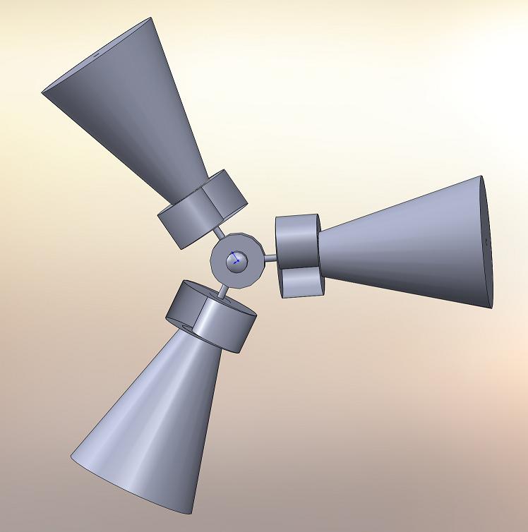
Each "blade" is free to rotate on its axis. The inner section of each blade is a Savonius rotor. The wind catches in the Savonius rotor and rotates the whole blade assembly.A tail aims the array into the wind.As the conical section is rotated by the Savonius rotor, the Magnus effect begins pushing sideways on each rotor, at 90 degrees to the central axis of the entire wind rotor assembly.This causes the multiple rotor "blade" assembly to rotate around the central axis, and power is taken off as normal for a windmotor.The same effect that curves the ball in flight pushes the cones sideways.No air is allowed to flow through or into the body of the Magnus rotor cone.This is a somewhat simplified concept. I'd like to build just one of these rotor "blades" and mount it with a counterbalance to test it out.I think the "real" design for the Magnus rotor would be a cone with helical ridges to act as the Savonius rotor component, to make the Magnus rotors auto-rotate in the wind.The point here is that these shapes can be made with thin sheet metal with simple metalworking tools. No high-precision is required... just good mechanical tools and bearings and so forth.
-
The design needs a little more development before I want to start cutting metal.And right now, I want to devote what free time I have to getting the Liberator documentation done.Here's another version of a Savonius/Magnus wind machine:The size of the Savonius components relative to the size of the Magnus rotor components needs to be determined, probably via experimentation.The Savonius rotors need to be enough to start (and keep) the Magnus rotors turning, then the Magnus rotors will make the whole array rotate about the central axis, and power can be taken off.This version has the advantage that it's well balanced for mounting on a tall pole or tower, and doesn't require aiming into the wind to start turning.Attachments
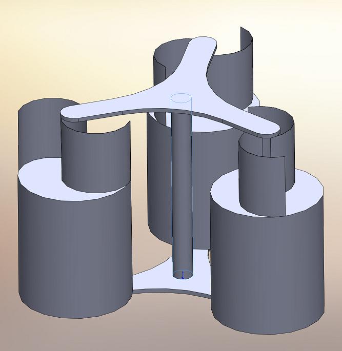
Vertical Axis Magnus Savonius Wind Machine Design.JPG 31K -
The horizontal axis array I drew up has a diameter of 3m, and, built out of 28 guage steel and with 1.5" central pipeaxes, the three rotors together weigh less than 77 pounds/ 33kg.That's with no hub or drive mechanism, but it should give you an idea how light weight this system is.If you scale it up too big, it will have to be made stronger, with ribs and struts and things to keep its shape.Much smaller, and I'd think it wouldn't produce much useful power.The vertical axis system could be made almost any size. Even if very heavy, it would have a sort of flywheel effect, and keep turning even during lulls.With the vertical axis system, you could make each rotor entirely of the Savonius type, and I think you'd still get the Magnus effect of the whole array turning. I'm not sure where the break-even point is between efficiency and complexity.A system that's all cylinder would require a motor to rotate the Magnus rotors.A system that's all Savonius split-barrels is going to catch less wind force usably. I think. I don't have the math to analyze it properly.
-
As lightweight as this system is, along with the ability to make it out of scrap materials, makes it an extremely feasible idea for an open-source wind turbine. On top of that, it's just plain cool.Andrew
-
My impression on the topic is that wind-powered generators are more useful if they can be activated by low speed wind. This design looks like it would have a lot of inertia, so it wouldn't start spinning until the wind really picked up.Also, are there any wind turbines that aren't effectively open source? They're just blades. Some of them get a little complicated, but it seems like you could get an 80% solution by just looking at them. Hell, people have been pumping water with wind power for (what seems like) forever with this thing. http://www.turbosquid.com/3d-models/historical-wind-pump-windmill-3d-3ds/333448
-
It seems to me the low wind speed problem would be the reason for this vertical-axis design. It's less efficient than a traditional turbine, but it spins almost constantly.
-
I think the second design is more complicated than the first, because one module affects greatly the other twoThe first choice looks pretty weird, but I think it could work. I know a bit about aerodynamics and calculation, so I'd be glad to help if you're trying to make some math firsttake care
-
wait im a little confused now? each blade spins independant and then runs a central hub?wouldnt that be kinda counter productive as the load is on the central hub and thus the outers will be spinning without transferrign the energy to the central point??the blades are the hardest part but ive seen some simple alternatives that follow the real deal, or set up one of the originals and just put it though the 3d printer?
id expect the generator to be the hardest part, expecially to make it efficient -
If it's simple to build then it's simple to test. Just rig one up, have it spin a salvaged alternator, and see how long it takes to charge a battery (or whatever, maybe a multimeter would be better).


Howdy, Stranger!
It looks like you're new here. If you want to get involved, click one of these buttons!
Categories
- All Discussions1,013
- General Discussion895
- ↳ Introductions145
- ↳ GVCS Development43
- ↳ GVCS Replication14
- ↳ Similar Projects, Partnerships and Open Culture53
- ↳ In the News14
- ↳ Education15
- ↳ Food18
- ↳ Energy42
- ↳ Health2
- ↳ Sustainable Architecture21
- ↳ Transportation10
- ↳ Household6
- ↳ IT, Web Infrastructure110
- ↳ Shared Personal Notes1
- ↳ New Communities10
- ↳ Other Languages34
- Project Management4
- Proposal and Development Status10
- Organizational Development26
- ↳ Team Logs4
- ↳ OSE Core Team1
- ↳ OSE IT - Core Team2
- ↳ OSE Collaboration Platform - Core Team6
- ↳ Resource Development3
- GVCS Technical Development52
- ↳ Open Source Car10
- ↳ Open Source Tractor1
- ↳ Gasifier Burner1
- ↳ CNC Torch Table5
- ↳ Agricultural Microcombine4
- ↳ Dimensional Sawmill1
- ↳ Documentation and Instructionals18
- OSE Dev0
- ↳ Trucktor0
- ↳ Microtrac0
- ↳ CNC Router0
- ↳ CNC Torch Table0
- ↳ Bulldozer0
- ↳ Backhoe0
- ↳ Car0
- ↳ 3D Printer0
- ↳ 3D Printer Laser Diode0
- ↳ Tractor0
- ↳ Powercube0
- ↳ Brick Press Controller0
In this Discussion
- andrewsanford May 2012
- Conor March 2011
- DavidDecent March 2011
- Matt_Maier May 2012
- nottern May 2012
- spike May 2012
- Wolfrick March 2011
Tagged
- wind 7
- greenpower 2
- savonius 2
- magnus 2
Loading