-
Hi,
I designed a simple model for a CEB 3D Printer last night – this can be built for under $500. Attached description as pdf...
A short outline of a CEB 3D Printer as a project: - Buy parts (x4): cheap powerful 12V motors, speed controllers, pulleys, bearings, encoders. - Build end effector/gripper. - Build conveyor for CEBs. - Test encoders, test position commands, test gripper. - Develop program to turn desired house/wall size into an array of x,y,z coordinates (easily done with Processing+Arduino+Firmata)
I rushed this model, so I have yet to figure out the details. I also made a quick simulation in Matlab (link below). Let me know if this project has been done/attempted before, criticisms, or if you’re interested in building.
Attachments
CEB 3D Printer Description.pdf 182K -
32 Comments sorted by
-
Welcome.
Honestly, I think you will find that there are too many variables involved in building such structures for this machine to totally finish the job. There will need to be human hands there to place and level objects, Corner joints and window openings will be a challenge also. Never mind the application of mortar in between the bricks themselves.
I have looked at this sort of machine and wondered if it would be useful in a farming application. Imagine shallow plowing, seeding and watering with such a system. Might be a winner.
As for building with it, I think it might be handy as a fancy crane. You could use a small hanging carrier to bring a bunch of bricks right where they are needed. You could carry mixed cement or mortar or anything useful for that matter.
But as a CNC machine operator, I would not recommend running automated equipment while people are all around. If you can figure out a way for the machine to finish the job on it own, then it's a winner.
The Dawg
-
Thanks for the info. I need to do more research and I agree that people should not be in the workspace during the building process. My plan is to first get this done with ‘bricks only’ as a proof of concept. I understand that without mortar, the structure is useless so it’s something I need to think about.
Anyway, I’m going to put my money where my mouth is and build a 1/3 - scale prototype. I’ve been testing out a couple things and I think visual servoing the end effector will be the most effective feedback, if done correctly.
There are a couple reasons why visual feedback beats motor shaft encoders: Cameras see everything – the gripper and the object to be pick-and-placed. Appropriate algorithms can differentiate objects and get a centroid and moment so the gripper picks up a brick by the center of gravity and knows the angle (relative to the fixed coordinate system) before it is released. I saved some video last night to illustrate:
- Demo
I’m going to go ahead with this prototype, so I’ll keep posting models/simulations here. I hope to have a roughly functioning demo by Sunday. Please keep providing info/potential challenges so I can get a better feel for the bounds of the problem.
-
Ok, the prototype is going well … hardware is made and I can manually control the end effector to
a position. Camera feedback is working
surprisingly well. I have two cheap
cameras looking at the x and y axes, so with one I can determine the x-position
and the other can get y and z position. In
my next post, I’ll link to a video of how I’m using computer vision to find
position and angle.For now, I’ve attached a very simple example of how control
laws are determined.
AttachmentsCEB 3D Printer Example.pdf 262K -
I uploaded a video of manual control of my prototype. The motors are being controlled by keyboard
input rather than the control laws explained in the previous post.Quick explanation: the video shows 4 windows, the top 2 are
Video
different views (X-Z and Y-Z) and below is each view with different algorithms
applied to find coordinates. I used a
red cup to act as the gripper because the red color is easy to find
with a camera.
-
@vc_nep
Nice video, I'm impressed. I noticed that you track axial orientation of the object being observed - that's very good, though I would imagine that symmetrical objects would be much harder to track that that regard. I also note that you are using a high contrast backdrop which greatly simplifies object extraction from the background. On site, things are likely to be much more complex. Still, very nice work. I would suggestion that you write this up in an OSE wiki page.
- Mark
-
Thanks, and yes, I wanted to make the contrast as easy as
possible to start. The algorithm is actually
double thresholding ‘red’ in RGB data as well as ‘hue’ in HSV so it’s more
robust than it looks. The trick is to
use bright green or pink with a real narrow band of HSV values so that
everything else is easily filtered out.
The plan would be to use several bright-colored markers
on the gripper and have a cam looking down at the X-Y plane so it will only see
the ground, base poles, the gripper, and bricks - this will avoid the
distraction of objects off in the distance.
Some bad news, as much as I hate when people start a project
and don’t finish, I need to work on a thesis and don’t have time or money to
continue right now. To scale this up, one
would need motors with at least 3000 oz-in torque, which require up to 30 amps
each and respective speed controllers to handle the power. My current
setup is about 4’ x 6’ x 4’ and lifts a gripper about 1lb., motors are 5$ each (solarbotics),
total setup ( < 50$).
I looked around online to get ball-park estimates to scale
up (12’ x 18’ x 10’ and lift 10-15 lbs):
Motors (26$ x 4 = $104) http://www.robotmarketplace.com/products/AME-210-1012.html
Power Supply ($260) http://www.robotmarketplace.com/products/0-AC-DC-1000W.html
Speed Controller (30$ x 4 = $120) http://www.robotmarketplace.com/products/0-SPDMX-40.html
Webcams I used: Logitech c160 ($20 x 2 = $40)
Wiring, Motor Hubs, Cable Reels, Cable, Pulleys (>30 lbs.
limit), Bearings, Motor Mounts, Base Poles (> $ 150 ?)
And for the sake of more accurate feedback, I would also
recommend optical encoders ($20 x 4 = $80)
Total: >= $ 784So my original estimate was optimistic. Anyway,
I'll post any future progress here if I can get EWB or a robotics club
to help continue this project.
-
Just an update to this project:
I had some time to work on another animation for a gantry robot that is more all-in-one self-explanatory. Although I started a wikipage for this project, I didn't really like the formatting so I put everything on it's own site (link below). If I come up with anything new, I'll post here. Anyway, let me know if anyone plans on building one of these, I still think it's worth pursuing. Thanks.
Site: Automated Construction with CEB's
Video:
-
I think a self-contained machine that presses the bricks and lays them would have a lot more success than this kind of pulley setup.I imagine a self-propelled CEB (or any other material) machine that builds a wall and scaffolding at the same time and then uses that scaffolding to follow the contour of the wall pressing and laying bricks.The disadvantage there is of course getting fresh dirt or other materials into the machine but if the scaffolding is in place the CEB could be programmed to go to the same spot every time it's running empty to fill up. Kind of like a roomba goes to fill up it's battery. With a large building multiple dirt filling stations could be setup.The advantages are:1. Any size structure could be built.2. No need to setup any system of pulleys. Just the concrete foundation would be enough.3. Because the bricks are being layed by a machine it gives you the existing infrustructure to add new components to that will smother the brick in mortar, place it properly, do any leveling, etc. It would be much harder to include those components into a gripper which ideally you would want to keep as light as possible.4. Much safer than a pulley system that would effectively close down the entire build site. A rolling brick layer would only occupy it's foot print on the particular section of the wall it's currently working on.5. Weight of the rolling brick layer could be utilized in pressing the bricks into the wall making sure there are no air pockets in the mortar and that 100% of the surface area is fully covered. Layers and levels would continually be used to monitor the wall for level and straightness. In some way this would be eating your own dog food, since the rolling layer needs a solid wall to move around it has an incentive to build a solid wall (rather the engineers have an incentive to make sure the roller builds a solid wall to sustain its own weight). After a 1,000 pound machine has rolled back and fourth on your wall a couple hundred times successfully you know you've got a solid wall, straight and level.6. You can have multiple brick layers operating at the same time.There are probably many more advantages.
-
Sorry for the delayed response, I haven't had time to reply recently.
As much as I agree a self-contained system would be ideal, where everything is attached - CEB press, conveyor, automated laying system - there are a few practical issues and I've separated an explanation into several parts:
//__________CLARIFICATION_OF_MY_CONCEPT___________//
The pulley system, cable array, or gantry would be carrying bricks, taking a predicted 20 seconds back and forth to pick and place bricks from conveyor to any position in the workspace, essentially taking 1-3 days to build any structure depending on the size. The process should be totally automated where the workspace is completely closed, so operation would stop if human workers enter the area. In a perfect world, the robot would not make any mistakes and so their would be no need for human intervention in the process. Power & Speed requirements: This isn't a gantry system that needs to be slow and manually operated to transport a 500-lb. engine, it would be much smaller with respect to power requirements and therefore faster. For specs, I'm predicting needing 12V motors with atleast 50in.lb of Torque @ 500 rpm and electric power transmission coming from 12V batteries with between 10-20 Amps of current draw. Also, the workspace dimensions I had in mind would be 12' (w) x 18' (l) x 12' (h).
My expectations of initial performance are quite low and that the system will require much rework and testing. From the time it is setup to run, it would be a miracle if it worked the way I proposed in animations after a month of tuning. Compared to human performance, obviously it would be much worse. The advantage is that once the concept has time to develop and because it can be so cheaply fab'd, the software (which is free) can be updated to improve performance without any labor cost.
Lastly, I'm not committed to one idea: notice I've changed from "cable array" to "gantry" already so I'm glad we're brainstorming. I think the whole automated brick-laying idea is an important one to develop, build, test, etc.
//__________CRITICISMS_OF_MY_CONCEPT____________//
I wanted to convey a few problems with my own concept so any newcomers are aware of potential practical issues. I can name about 10 problems off the top of my head:
- no mortar solution yet
- potential communication issues with gripper
- wires of any kind, even pig-tailed and stranded will wear out over so many translations
- so… use wireless communication - bluetooth has proven to be good within this distance, but continuous wireless communication is never guaranteed
- As you mention, any additional attachments required will add weight and complexity
- wear of motors, pulleys
- battery life
- method of recharging if using batteries
- lack of a perfectly global system unless computer vision is used (as I demonstrated in previous video), although I have more faith in encoders if there is not much deflection with rest of system.
- if CV is used, the resolution is limited, as demonstrated in my video
- With both cable and gantry, there will be almost straight horizontal force of maybe 5-10 lbs. on the end of the top poles = 5*12ft = 60 ft.lb torque at the base => danger of poles tipping over or atleast deflecting badly unless mechanical system is redesigned.
//__________CRITICISMS_+_RESPONSE_TO_YOUR_CONCEPT_________//
In general I understand the mobile part, but unsure of the rest of it, so perhaps you could hand-draw and scan a picture so I can better understand it.
1.) "any size structure can be built" - width-length-wise I agree, but I'm not understanding height without an illustration of the machine.
2.) The machine will only need to be assembled once.
3.) Yep. Agreed, still thinking about that.
4.) Actually, shutting down the workspace is the idea and I should have clarified this in previous posts. The goal is to develop a system that can build everything autonomously after being given something similar to a .STL file to build a structure. Again, I'm aware this is easier said than done.
5.) Need illustration to really understand. "a 1,000 pound machine","self-propelled" - This is a third the size of a car and would need the respective power requirements. When you're building a one-of, this simply takes a lot of power so that speed controllers, motors, batteries get exponentially more expensive. This, along with the sensor problems mentioned below are my main criticisms of a mobile self-contained idea. If you can come up with a ball-park number for mechanical torque/power requirements for overcoming static and dynamic friction a couple thousand times, that will be helpful for comparison. In the meantime, I'll try to come up with and justify my own number, (e.g. ~10,000 Watts to move 4 motors+gripper > 3000 times).
6.) Again, illustrate.
//_____AUTONOMOUS_MOBILE_ROBOTS_OPERATING_OUTDOORS_______//
Here's the problems with mobile robots:
- Sensors: It's fun to say, "Well we need global position, hmmm…GPS? - done!".
- I've used digital compasses, gyros for dead reckoning, GPS, LADAR and all of them have many flaws in this scenario so I will describe them. Digital compass is not accurate enough and they depend on where you are. Gyros inherently just integrate an error over time (even $1000 ones used in vehicle research get too far off after 5 minutes and must be reset). Cheap GPS is not accurate to within inches and so not really useful for laying bricks next to each other, LADAR (very accurate, but good ones are upwards of $2000 and there is lots of data to exchange and wouldn't really help without 3D reconstruction algorithm).
- I'm well aware of and hugely interested in companies that use mobile robots successfully: Kiva, Harvest Automation, iRobot, etc. but I just don't think it's the best application here.
- Roombas rely on no-slip because there is decent friction, they move very slow, and use a well-thought-out algorithm developed at MIT. If you've ever taken one apart before, you'll notice the wheel encoders are also incredibly geared-up for insane resolution.
Wall following, which you described, is actually a way to maintain position accurately, but you would need a reference point to start out with. In my concept, the point is basically that even if the machine thinks it's facing North and it's actually facing East, the local coordinates used to build the structure will remain unchanged and build the whole structure properly in a local sense, even if the whole design is facing the wrong direction.
Also, just searching online I found a Prof. who developed a similar concept http://www-bcf.usc.edu/~khoshnev/Research/Research.htm. This is much more complex and expensive than the proposed system needs to be, but I like the fact someone else is thinking gantry.
//_________________CURRENT_PLANS__________________//
I might have 2 weeks of free time to now devote to this:
1. I'm redesigning a mechanical model
2. Importing to HyperMesh to perform FEA in order to justify a low-deflection assumption
3. Then, without actually building, I'm going to try to generate a more specific design than the fantasy animations I've been posting.
4. If anyone wants to brainstorm this idea to death, an IRC channel (http://opensourceecology.org/wiki/Irc) seems to be a more efficient way to communicate. Temporarily, I'll plan on being on 5PM EST every day this week.
-
That's a cool idea. I particularly like the wire design because there's no need for long expanses of linear guides that have to be supported.Looks a lot like the Skycam that gets the camera right down onto the scrimmage line. http://en.wikipedia.org/wiki/SkycamYou could mount a structured light http://en.wikipedia.org/wiki/Structured-light_3D_scanner scanner on the grabber to get micrometer positioning accuracy in all dimensions.You could use this cheap jamming gripper http://www.instructables.com/community/Robotic-Gripper-Runs-on-Coffee-and-Balloons-Get-/ to pickup the CEBs and anything else lying around.If you make the pillars taller you could stack several of these wire brick movers on top of each other. You'd just need a little more code to keep them from running into each other. At a minimum that could double your throughput.If preparing the top of the CEB for good placement and adhesion turns out to be a problem then the people monitoring the robot could just walk around spraying the bricks down and scraping the tops flat.Construction shouldn't be too difficult. You could lay out a pillar and fix the base to the ground, then attach two shorter support struts. Fix one at a 90* angle and lever the pillar up onto it (so it's at like 30* parallel to one wall) then get someone to walk that strut towards the base until it and the second strut are 45* to the pillar. Then fix the struts to the ground. Connect the tops of each pillar with a truss wire (before lifting the pillars up) and you'll have a rigid temporary structure. You might even be able to do all that INSIDE a tent so that when you're done the entire build area is enclosed. You might have to make one side taller than the other if you do that so rain and snow slide off.
-
Accuracy of GPS:GPS is quite accurate (+/- 0.25 inch) when you're using high precision GPS receivers and a reference point that is fixed and not very far away - for instance, an antenna on one of the builder machine's posts vs. the position of the positioning head would probably tell you at least which brick you're positioned at.
-
Some more comments regarding self-contained layer:1. Upon thinking about this, it probably doesn't make sense for the self-contained layer to also make the bricks. This should cut down on weight/power requirements of the layer significantly and allow some human inspection of bricks before they are layed. So, when the brick layer comes up to the fill station it would be loaded with bricks instead of dirt. This may complicated the loading process a bit more but I think the gain in division of labor and more compartmentalized approach may be a win.2. I don't see any need for GPS/compass. I see the "tracks" being done as part of the foundation laying process. One way to kill two birds with one stone would be to use special forms for the foundation that will also double as tracks/ for the brick laying machine. One way to do this would be to have the forms leave a groove in the concrete of where the bricks will go. Then the layer would simply follow that groove. Alternately if we're just doing outside walls then the layer could simply use the outside edge of the concrete pad as the guide. Worst case, the first layer of bricks could be manually done by having a human walk the machine and control the layment. After the first track is done, the machine could just following that first course.
-
@Matt_Maier Yeah, so this would be the Skycam with a gripper. Thanks for the gripper links btw, (I haven't designed one yet) and also the wiki contribution. I started a page a couple months ago, http://opensourceecology.org/wiki/CEB_3D_Printer, but haven't had time to update it until now, so start checking it this week. And a tent or tarp is a good idea for weather-proofing and safety. I'll have to think about how adjustable the structure should be and I have an idea for an adjustable redesign, just need to renew a CAD license tonight.
@DavidIAm, On second thought, I wouldn't rule out GPS. I know Deere, CAT, and so many others use them successfully for similar applications, so I'm going to assume I'm wrong about cheap GPS until I do more research on what's available. I just personally haven't seen them that accurate, although close. The problem is that I would expect the position requirements to be +/- 0.1" in order to work.
@eukreign
1. Yeah, human inspection is something I kind of ignored so I'll try to come up with a feedback plan on how things are validated, e.g. If the machine messes up a bottom brick without human supervision, how will software determine to stop before building a new layer.
2. I feel like you're onto something conceptually and I'm still interested in seeing some sort of sketch/illustration or link me somewhere with a similar example.
Again, I'll be on IRC (http://opensourceecology.org/wiki/Irc) all day today and probably everyday this week to discuss a plan to design and build. -
Part of quality is testing - the machine merely must not be able to place a brick - but through a different system, measure if the brick is in the right place. The feedback between these two systems is the quality control.The typical robotic idea of 'move with precision and you don't have to check your accuracy' is a shortcut for the sake of simplicity in software. I think that the innovation that will truly make such robots reliable and precise is to operate them on feedback loops - so what if its 1800 steps this time, and 1858 steps next time? Its irrelevant if the imprecision of the motor skipped a few steps as long as its still positioning things relative to the position they're supposed to be.If you have a visual alignment system, a GPS positioning system, and a feeler-comparator attachment, and a step counter, the interaction of those systems will give you quality despite your slop, enabling industrial class results with hand-made slop.
-
@DavidIAm, Exactly - fix poor mechanics (motor transmission gears skipping, variable stress, weather-related effects) and other unknowns with feedback control in software. I added PID control loop sample code on the wiki page last night for doing so with rotary encoder feedback (= "step counter"). Same can be added with GPS feedback and kalman-filtering the two. Deeper kinematics & control explanation here: https://sites.google.com/site/automatedconstruction/control.
Note: everything will be moved back to the wiki this week. Also, more of a rough development strategy has been posted on the there as well. CAD license renewed last night, so design work should be on the site by tonight for a more detailed view.
http://opensourceecology.org/wiki/CEB_3D_Printer -
See attachment for a very crude drawing.Basically this setup would require a double wall construction where each course serves as a track for the brick layer and insulation goes in between them. The initial track could be done either by navigating around the foundation slab or by having a human manually walk the device (especially for interior walls). After the first layer is done the layer could operate autonomously using the layed bricks as tracks.I have not thought of how it would climb from one layer to the next or how the laying mechanism would lay bricks and mortar them (if necessary).Attachments
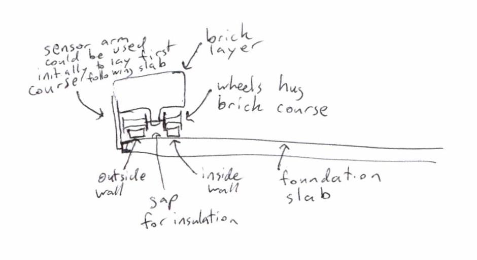
12202011122549_001.jpg 30K -
Some things that would still need to be resolved with self-propelled brick layer:1. Turning on 90 corners.2. Climbing up/down brick layers (climbing down may necessary if it's going back to fill station to refill).3. Actual brick layment process.4. Mortar application.5. Loading bricks onto machine.6. Last but not least, getting the machine down once it finishes laying the top floor :-)
-
I don't know if anything at all is transferable from this machine but I think it's inspiring: http://www.tiger-stone.nl/
-
I think that automatic placement bears some consideration on strategy for the end result.Now, that may be a bit extreme, but consider: The entire reason that we're making bricks *at all* is because we can automate the creation of the blocks but not the placement - they're designed to be manually placed fairly rapidly.If we're going to automate the placement of material (that is the eventual goal of this discussion, right?) then it bears consideration that blocks (designed to be a unit manipulable by a man) may not be the best way of doing it. Blocks make a masonry structure which has weak points between every single block. What is the logic behind making a structure that is masonry-weak when we can make one that is monolithically strong?Adapt the rammed earth formwork technique to a slipform such as is used for concrete work.Your unit moves into place (I visualize by gantry crane), clamps its sides close, starts spraying granulated (as in fluffy broken apart) earth into the form. Rammers move within solidifying this into a hard mass. When the prescribed lift is complete, the sides unclamp, the unit is moved to the next position, process repeats.The complexity of the rammer-clamper is fairly limited and the matter of delivering granulated earth to any point on the site is easily accomplished by conveyor if not tubes and blowers. Its a green version of the concrete-extruding robot gantry that we've seen on youtube. It just extrudes monolithic earth walls.Then there's the consideration that if people aren't going to be handling the blocks, why are they so damned tiny? Giant Compressed Earth Blocks are the logical progression. If they're going to be moved by a robot, the strength of a robot machine can move giant things much more efficiently than many small things.Is solving the automated positioning of thousands of small bricks actually the shorted line between 'a pile of dirt' and 'an earth house'?
-
The wiki has been updated with Actuator & Feedback Architecture, a logic flowchart, high-level source code, and some example source code for individual functions. CAD screenshots will be up in a few days (I have license, but no program yet).
Upcoming also is:
- easy-to-read schematics for specific low-voltage wiring
- working, ready-to-download source code for testing
- an executable program to generate a text file with "solid shape-to-discrete-brick" coordinates. Actually this is already complete as a proof concept, but needs work. I might put it up anyway.
- better organization of wiki, with dynamic linking, to make it easier to read through content.
http://opensourceecology.org/wiki/CEB_3D_Printer
-
(click on "Insert Image" and paste the image url, which is http://opensourceecology.org/w/images/c/c2/CEB3DP_Wiring.png - see result below)

-
Helpful tip: To learn the URL of an image from the wiki, go to the image's page (like http://opensourceecology.org/wiki/File:CEB3DP_Wiring.png ) and look for the Full resolution link.
-
Explanation in Q & A format to handle expected questions:
Q: Why such simple design?
A: To cut down on fab cost/time and material.
Q: So someone pushes these to a location, what then?
A: Stake-like mounts on each base will drive into the ground, essentially holding the tires up so the whole system is fixed in place.
Q: How?
A:
Q: But they will never be placed perfectly, so won’t this screw up the coordinate system?
A: After the home position sensor routine, a calibration routine (detailed below) checks exactly how far the system is off, software adds the off-ness as the new coordinate system.
Q: Ok… so what if someone places them like this accidentally?
A: From the home position sensor routine, the only things we know for sure are the cable lengths, like “1-2”, “1-3”,”2-4”,etc.
Lengths which should be the same can be averaged, so that for example: the distance between 2 & 3 should be equal to [“3-2” + “2-3”]/2. This will give us “a”,”b”,”c”,”d”,”p”, and “q”, but we don’t know the angles in the blue yet.
Law of Cosines tells us things like:

Q: So you know how much the local coordinate system is off by, how do you update the coordinate system?
A:
Note: A worked example, (math and source code) will be posted to the wiki.
Q: And then just by using the new coordinate system, all other routines remain the same?
A: Yes, they are just based on calculating Pythagorean Theorem in 3D using the new coordinates.
Q: Will the operator need to know/worry about the home sensor routine and calibration routine?
A: No, in automatic mode, as soon as the process is started the machine will calibrate itself. -
Interesting idea. My first thought is that it would unnecessarily limit the range of structure sizes and shapes the printer could produce. The skycam has wires that run all the way across a stadium, so the length of cable isn't a design limitation. Why limit the width of the build area?I don't think you're going to get enough benefit out of combining two pillars on one base. It's a good idea to assume the area in which these will be deployed will be rough, so no one's going to roll them into position. They'll be carried over uneven ground and then put in place, but that means they'll need arbitrary bracing to deal with the arbitrary ground shape, uneven surface support, and unpredictable winds.It looks to me like, to keep costs down, the pillars won't be built strong enough to resist side loads on their own. Instead it would be more efficient to anchor them in place and then pre-load the tops by pulling them all in together against their supports. That would be the cheapest way to eliminate play in the system. It would also be more flexible in potential applications then putting two pulleys on a common base.Although, you could get a similar result using your new approach by attaching tie-downs to each pulley end of the upright and staking them to the ground. That would pull the whole thing down into that spiky baseplate and anchor it against side loads. You'd still have the unnecessary limitation on build volume, tho.
-
In an effort to prove my concept is feasible, I actually proved it will not work (at least the gantry). Here's why:

Over angles 1 to 90 degrees, the tension force in the x-direction was calculated and plotted below:
@Matt_Maier, this means I can't reasonably justify that the baseplate will "anchor against side loads", so you are right. This also means that the cable design cannot dip below an angle of ~20 degrees unless there is a support beam in the middle to handle the compression, which (if there was) would open the concept up to many more possibilities, but would also limit the height range.
But also, to answer your question:
The name of the game is to bring this project out of fantasy land (where it is now) into a feasible concept. By referring to a stadium, you are actually imposing a limit as well, albeit to the massive volume of a stadium. But also, a stadium has the workspace to use already - pieces of rigid metal 200' in the air. If I had that, this project could be well under way. But that brings up an interesting idea anyway. I arbitrarily chose 18'x12'x12' and it could be larger; much larger: 200'x300'x400' let's say.
So my challenge to you is:
Come up with a reasonable design for that volume and describe it in detail: specs, mat'ls, cost. And with a larger volume, remember the usefulness is exponential (i.e. you can build a whole hab lab/large structure) so the cost used to build it is less of an issue. If you think it needs to be smaller, how large can it be and again, how would you build it?
-
@Matt_Maier, here's my solution to your suggestion/my challenge:

Fabricate four very high poles somehow, cement them far into the ground, and constrain with wires the same as you would a high telephone pole or bridge structure. Since you wouldn't trust encoders with this much cable length (stretching), revert to @DavidIAm's suggestion to use GPS. But you can still use the same motor specs and control loop and just throw out encoders.
So this would be known as the "Village-Wide Cable Construction Robot" concept and from the stress analysis above, you can chart this at high angles - meaning you will find relatively low horizontal forces = reasonable range. You would be able to jog it for manual control and after enough testing and confidence in software, use it for automatic control to pick-and-place everything in the whole village.
-
Now THAT's an interesting idea. I had been thinking about the Skycam but it hadn't occurred to me that, if it works, then you could scale this idea up to cover the ENTIRE village. That would make the idea about multiple grabbers even more useful.The reason I keep mentioning skycam is that it looks like the closest commercial equivalent, which makes it a good starting point and a good comparison for cost/performance metrics. A few interesting things I've discovered:* It's out of patent http://www.google.com/patents?id=Lh43AAAAEBAJ&printsec=abstract#v=onepage&q&f=false although they seem to still be issuing patents for this kind of thing http://www.google.com/patents?id=OJgVAAAAEBAJ&printsec=claims&zoom=4#v=onepage&q&f=false and there's one that works like that other design you made an animation of http://www.google.com/patents?id=MZkhAAAAEBAJ&pg=PA14&dq=4710819&hl=en&sa=X&ei=7jD1Ttj6CaOXiAK--cijDg&ved=0CDkQ6AEwAg#v=onepage&q=4710819&f=false Then there's this guy who seems to want to patent every possible arrangement of cables and pillars that could make up a crane http://www.google.com/patents?id=SqKFAAAAEBAJ&pg=PA23&dq=4710819&hl=en&sa=X&ei=7jD1Ttj6CaOXiAK--cijDg&ved=0CEsQ6AEwCA#v=onepage&q=4710819&f=false* some systems seem to use 4 ropes and 4 reels, but at least one uses 3 reels and 2 (really long) ropes. The former is what you've been designing; the latter uses one rope for x, one rope for y, and gets z when the 3rd reel move both ropes together. http://www.google.com/patents?id=84B6AAAAEBAJ&pg=PA2&dq=4710819&hl=en&sa=X&ei=gDL1TuLHBsvMiQKLpaGiDg&ved=0CDEQ6AEwADgK#v=onepage&q=4710819&f=false* It doesn't use steel cables. Instead it uses kevlar rope. Lets just say that's $2 per foot (an educated guess). If you wanted to move it around over an entire football stadium that's around $10,000 of rope. A bigger area would mean a proportional increase in the cost of rope. However, the other costs (motors, pillars, etc) wouldn't necessarily increase all that much.Basically, I don't think it's worth worrying about a village-sized wire crane thingie just yet. No one's going to shell out that kind of dough until they've seen it work at a smaller scale. I do think it would work. Whether or not it would be cost effective at that scale would have a lot to do with how long the rope lasted. It would be a good idea to investigate the possibility of building structures near each other so that you only have to move half of the pillars to build a new structure.You know what...that gives me an idea.
-
Another idea to brainstorm: A CEB 3D Printer as an attachment to the LifeTrac.
Don't let the setup in the video below limit the concept. For example: the attachment wouldn't have to use cables - could be a rigid gantry system or an industrial robotic arm or multiple arms.
The advantage here is that it satisfies several requirements I had in mind:
- being mobile
- already has a power supply - the LifeTrac's modular supply
- has a seat for the operator to sit in when in 'manual' control mode
- maintains a local coordinate system when parked
- is rigid so no real calibration is required
- also: might start a trend to make the LifeTrac's actuation arm modular (if it isn't already).
By the way, this is probably my last post again for a while. If you'd like to continue brainstorming, the following wiki's have a decent base of content to edit and build upon:
http://opensourceecology.org/wiki/CEB_3D_Printer
and Matt Maier's:
http://opensourceecology.org/wiki/Automated_construction
-
well ... just to add my two cents.
If you want to build something that looks like a large printer/CNC machine you first and foremost need to think about stability of the supports. Unless you install some sensors that would be able to correct any movement of the base frame you need to make them as rigid as possible. Just looking at the designes so far I would be afraid the whole frame could just flip over, not to mention remain the required millimeter-scale accuracy .
Generally as with 3D printing it's worth while when you're doing something hard to construct other wise. Straight walls are best build out of small, prefabricated parts (could be as small as a single brick, could be a whole wall section).
I think the whole open source village idea is to help people who are poor build a house from the ground up with minimum resources. What poor people generally have in an overabundance is time and the will to work. What would be the benefits of using this 3d printer for them? They could just spend a day doing the brick work by themselves. The option is to automate the process for an additional cost. What's the benefit? ... So as much as I'm sure we will see very soon commercial "3d printers" used in the construction industry I don't think that it's going to be used for building basic shelter for the poor. Rather pushing the bouderies of what's feasible and coming up with some very organic designs.


Howdy, Stranger!
It looks like you're new here. If you want to get involved, click one of these buttons!
Categories
- All Discussions1,013
- General Discussion895
- ↳ Introductions145
- ↳ GVCS Development43
- ↳ GVCS Replication14
- ↳ Similar Projects, Partnerships and Open Culture53
- ↳ In the News14
- ↳ Education15
- ↳ Food18
- ↳ Energy42
- ↳ Health2
- ↳ Sustainable Architecture21
- ↳ Transportation10
- ↳ Household6
- ↳ IT, Web Infrastructure110
- ↳ Shared Personal Notes1
- ↳ New Communities10
- ↳ Other Languages34
- Project Management4
- Proposal and Development Status10
- Organizational Development26
- ↳ Team Logs4
- ↳ OSE Core Team1
- ↳ OSE IT - Core Team2
- ↳ OSE Collaboration Platform - Core Team6
- ↳ Resource Development3
- GVCS Technical Development52
- ↳ Open Source Car10
- ↳ Open Source Tractor1
- ↳ Gasifier Burner1
- ↳ CNC Torch Table5
- ↳ Agricultural Microcombine4
- ↳ Dimensional Sawmill1
- ↳ Documentation and Instructionals18
- OSE Dev0
- ↳ Trucktor0
- ↳ Microtrac0
- ↳ CNC Router0
- ↳ CNC Torch Table0
- ↳ Bulldozer0
- ↳ Backhoe0
- ↳ Car0
- ↳ 3D Printer0
- ↳ 3D Printer Laser Diode0
- ↳ Tractor0
- ↳ Powercube0
- ↳ Brick Press Controller0