-
Hi,
I bet a lot of you have heard of "The Solar Updraft Tower". If not, then here are a few links:-
http://en.wikipedia.org/wiki/Solar_updraft_tower
http://www.youtube.com/watch?v=C-EvV90MeDY
http://www.youtube.com/watch?v=yuOXgTC0SRc
Now suppose I want to build something like this on a much smaller scale, say, just big enough to provide electricity to a small household, maybe 300-500 Watts. I want to improvise the design since i think that the maintenance of a glass canopy would be too much hassle. Glass is expensive and breaks easily.
So I have some ideas. Suppose we lay down some metal sheets very close to the ground(maybe half an inch above the ground). We paint the top surface of this metal canopy black, so it absorbs sunlight and gets really hot(I think 60 degree Celsius is easily attainable in tropical regions like southern India). We spread these black painted metal sheets over an area of a few square meters(maybe 100). At the center of this canopy we make a hole and place a 10 feet tall chimney and inside the chimney we place a turbine. So I am hoping that heat absorbed by the metal sheets will be transferred to the thin layer of air underneath the sheets. The hot air will rise through the chimney and rotate the turbine.
Will this work? I welcome advice/criticism/suggestions/curiosity.
-
12 Comments sorted by
-
The 300-500 watt was just a rough estimation. So basically i want enough power to run a laptop for several hours during the day, a small refrigerator too maybe, with enough left over to charge the batteries to keep a few lights on for 4-5 hours during the night. I may also need to use a small water pump for a few minutes to pump underground water. How much power would be enough to do this?
Also, is the device technically feasible, even if I lower the requirement to 100 Watts?
-
You may want to read this article: http://en.wikipedia.org/wiki/Peltier_effect
-
Thanks. The article was informative, but it deals with thermoelectric effect which is mostly a microscopic phenomenon. My concern is mostly the mechanical aspects of the device. Will the air under the canopy get hot enough to gain enough velocity in order to drive a turbine?
-
Probably. It looks like the design is very easy to scale. If you're not getting enough power just make it bigger. Of course it will be highly dependent on having enough spare land and on appropriate weather.I'm not sure about replacing the plexiglass with black metal, but it seems cheap enough to just give it a try.
-
Thanks Matt Maier. These days I am looking for people in bangalore city who can help me with the technical aspects of design and construction. I hope i am able to build a prototype soon
-
You could probably get some more ideas and information from here: http://en.wikipedia.org/wiki/Stirling_engine
-
Hi Rajesh, reading the wikipedia page you supplied tells me that the cost of the collector+tower+generator would be much more than solar PV for the same power, even if you achieve the industrial scale efficiency of the 7km dia, 1km tall version they speak of, which is unlikely (I would guess from my understanding of fluid flow dynamics that the resistances of the scaled down version would reduce the collection rate by 10 or even 100 times). this based on the price we paid last year for PV (~€1/watt) and prices I've been quoted in the past for roofing steel sheet (~€5/m²). The black painted steel sheet would forfeit some of the advantages of the solar tower (able to grow food in the collector and heat storage for night) and at the same time would probably decay faster than the PV too (climate depending, if you're in a really dry place, maybe not!).
I hope I'm wrong and your idea works wonderfully if you try it. May I ask the reasons for you wanting to do it this way?
I spent some time looking into sterling engines a few years back and came up with a simillar concept to the one here in OSE of using reflective concentrators for high temperature heat collection with a steam accumulator for storage (8m³ could store enough for 6 months), sterling motor for electric conversion and various other direct heat uses for cooking, heating water and house, and heat powered fridges (amonia constant pressure cycle like gas fridge) for food and air-conditioning, storing day created cool for the night in an ice accumulator, too. All the energy needs of an European home served by its own roof. A 250°C prototype could be made using an LPG bottle for the storage (steam pressure at 250°C is 36bar, same as propane at 50°C, so should be safe enough) and old caravan fridges (we have 4, one from each of the 20 year old caravans we've been living in for the past few years) run happily from 205°C heat. Heat collection and storage can be better than 80% efficient, too, so anything that can be run from heat directly should be (in my opinion).
One other thought comes to mind - that efficiency number of 0.5% is the same as my estimate of the per land area efficiency of growing trees and using them as fuel. Now a tree is a truly high-tec device that is self assembling, self repairing, self adaptive to its surroundings, mitigates CO2, builds soil, provides food, moderates the environment.....
-
Yes. These are points to think about. But anyway my intention right now is to build a small prototype and see how it performs (not larger that 10-20 m²). I am not really sure how well it will do. I hope it's worth a try.
-
Hi Rajesh
I'm glad you're going to do it anyway, I hoped you hadn't got disparaged! It will do something, and the materials and
learning will all be useful to you in your future if you decide its
not that good. So I've put together some thoughts on how to maximise
the result. I apologise in advance if the level of my explanations is
too low or seems condescending, I don't know how much you or anyone
else knows about these things, or for that matter how much I know (I
am entirely self taught from Internet and books) - anyone should
feel free to correct me if my thinking is inaccurate.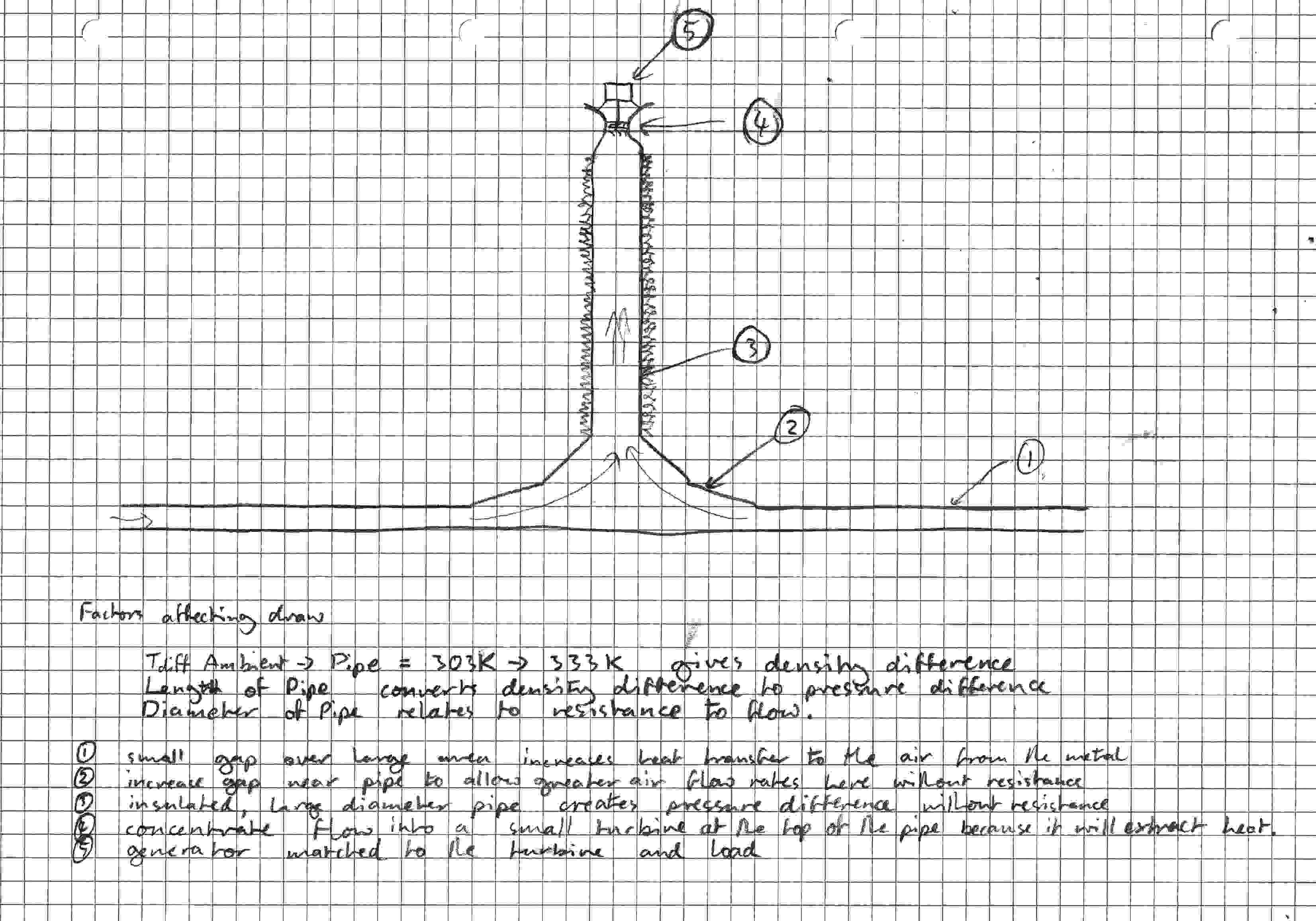
See file Diagram 1: whole system overview
1: Contrary to my earlier statement
about viscous resistance, get the main area of the collector as close
to the ground as possible, down to a total area not less than double
the area of the chimney pipe. If possible ensure that the ground is
as flat as possible too, although completely smooth will actual work
against you as turbulence increases heat transfer. the perimeter is
going to be so large that the actual velocity of the air at that
point will be tiny.2: Increase the distance between floor
and collector as you approach the pipe to maintain the 2*pipe area as
the circumference decreases. Also try to make the transition to the
pipe as smooth at possible as sharp corners create resistance to
flow.3: the length of the pipe is a delicate
balance between losses and gains. Insulating the pipe will keep the
gasses inside as hot as possible. Draw is affected by 3 things: 1)
Temperature difference between inside and outside give a density
difference (boyles law, density or pressure are related to absolute
temperature ie Kelvin); 2) The hight of the pipe converts the density
difference into a pressure difference that can be used to drive a
reaction turbine; 3) The diameter of the pipe affects the resistance
to flow drastically - about 10 times less resistance for a 50%
increase in diameter.4: Putting the turbine at the top may
not make any significant difference but it could do on 2 counts: 1)
theoretically the energy is taken from the heat in the flow so this
keeps the pipe gasses as hot as possible; 2) The turbine will
introduce turbulence into the flow which will increase the resistance
to flow in the pipe, and increase heat loss to the walls of the pipe.
The turbine should be fairly small diameter, to get a higher
rotational speed from the air velocity as this helps get better
results from a small generator. Concentrating the flow into it gives
it more air velocity and pressure to work with. (see Diagram 2)5: The generator mounted here needs to
be matched to the speed of rotation of the turbine at load and to the
voltage of the battery or fridge or whatever. It should be a
non-cogging type (sorry, no DC motors as the magnets grab hold of the
rotor when it's still and will stop the turbine from starting at all,
even with a lot of flow).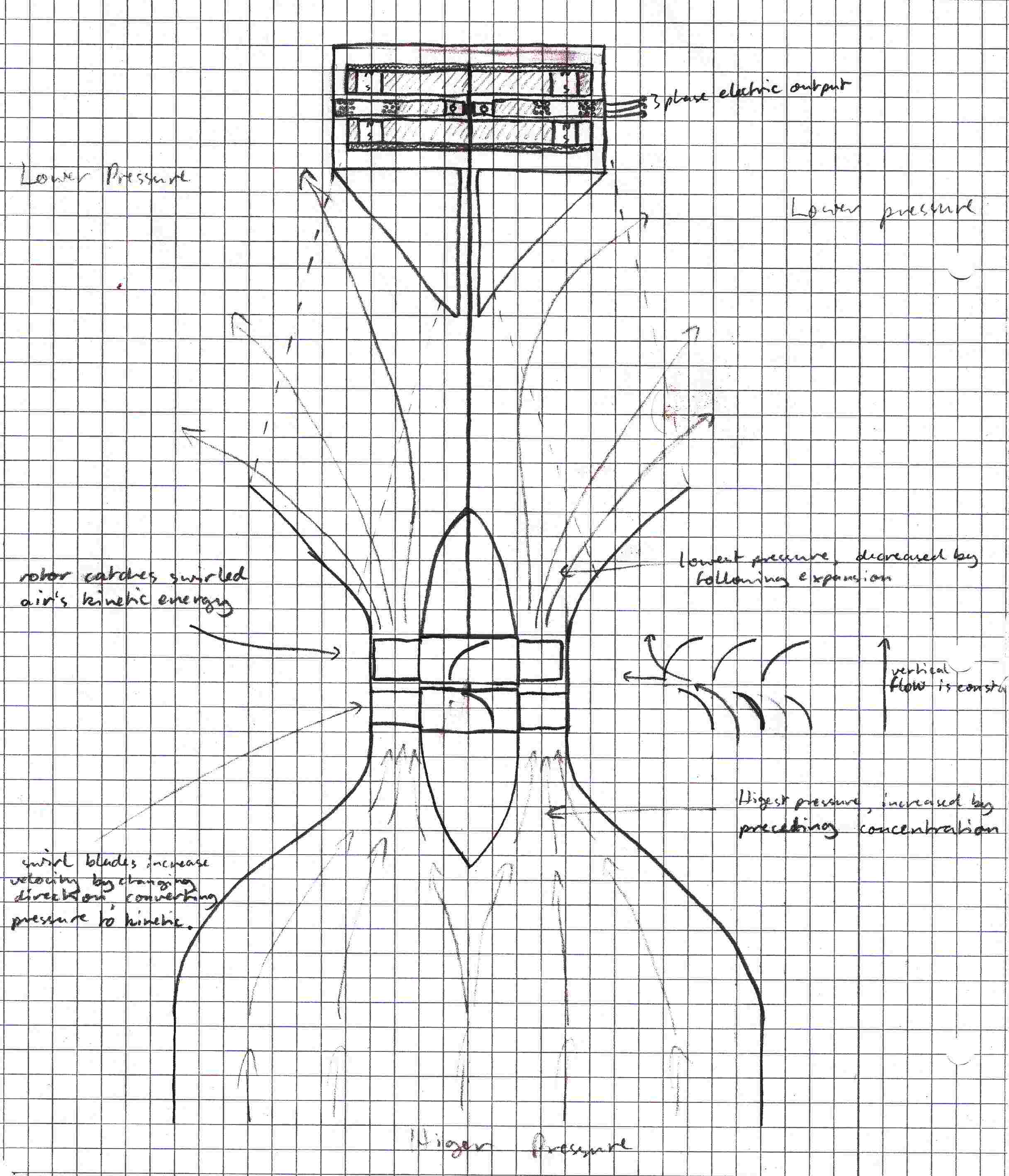
See file Diagram 2: Turbine and Generator
detailsIn case you don't know how a reaction
turbine works, you need 2 sets of blades. The first set is static and
speeds up the air with a rotational swirl, converting pressure into
kinetic energy. The second set of blades rotate and are pushed round
by the swirling air but the shape of them slows down the swirl to
near zero as they pass. The pressure has been reduced (cooling the
gas) and the flow volume remains constant up the pipe, as it must.I'm imagining this turbine being made
from a computer cooling fan for the rotor (~80mm diameter) and
possibly wood and sheet plastic or metal for the stator (cut curved
slots with a knife and fit the sheet into the curve). The lower
bearing of the shaft is within the central block of the stator (not
shown for clarity). Another cooling fan probably cannot be used for
the stator since the blades must curve the opposite way, and I have
never seen a cooling fan made to rotate that way. It is possible to
put multiple pairs of stators and rotors on the shaft, but may bring
little benefit except at startup.An expansion zone after the turbine
controls the expansion to realise some pressure drop in this zone,
and any swirl remaining after the rotor will increase this.The generator I am imagining is made
from stock plastic or plywood with some thicker mild steel sheet for
the top and bottom plates to assist the magnets, which are the 10mm
diameter 10mm thick ones I have knocking about somewhere. It is a
miniature version of Hugh Piggotts axial flux 3-phase generator. Cutting circles with a hole-saw gives a good circle with a hole in
the center. Drill 10mm holes for the magnets in the plywood and push
them in. Glue the sheet metal to the backs - these are the rotors.
The stator has the upper bearing in its center. use a larger hole-saw
to make this circle if available, drill large holes for the coils
(20mm? number of turns and gauge to be determined when you know how
fast its all going to spin, but the inner diameter is the same as the
size of the magnet) glue them in and cover with a thin smooth layer
of plastic (sticky-backed?) set the upper bearing in the center. Put
it all together on some threaded bar with a washer either side of the
top bearing to give some clearance. Fit the stator into a tube for a
case, sealing the top against weather (obviously). This then gets
supported far enough away from the top of the pipe to be out of the
way of the airflow.This won't make much power but will be
enough for a test run and can be scaled up with more/bigger magnets
and coils if it turns out there's more power available. The voltage
generated is determined by the equationequation 1: V= N×dΦ/dt
where Φ
is the total flux change in Webers, t is time in seconds and N is the
number of turns of wire.example:
my 10mm diameter magnets have flux
density of 0.45 Teslas. 1 Weber = 1 Tesla × 1 m², so total flux =
0.0000353 Webers.If there are 8 magnet pairs and 6 coils
(as Hugh Piggots design) then each coil will experience 0.000141
Webers change each 1/8th of a revolution. If the rotor is rotating at
20 revolutions per second this is .023 V/turn average. With 2 coils
in series and star wiring of all six this is .069V/turn. to get 20V
no-load output (remember I×R voltage loss in coils and wiring to
battery will reduce) to charge a 12V lead-acid or Nickel-Iron battery
therefore needs 290 turns per coil.The steel plates on the outside should
feed some of the flux from the back of one magnet through to the
front of its neighbours, but I don't know how much so have left this
out of the calculations.I have another design for a larger
generator which in theory has many advantages, not least that it
requires no more magnets than this one. It is a double generator with
the magnets static, generating a current in small rotating coils that
is used to energise larger electromagnets which spin round a second,
static set of coils as per above. some electronics is required to be
on the rotor but at a minimum this is just 6 diodes to rectify the
3-phase from the mini generator for the main electromagnets. It could
have a buck regulator as well to reduce the extra load when enough
current is already coming to saturate the iron of the main generator.
It has zero starting torque like the one above because the
electromagnets have little residual flux until the mini-generator has
started to turn, but many times the flux density in the main
generator allowing less turns of fatter wire and reducing losses. An
alternative is to use the lower starting RPM and high peak voltage
with a buck regulator matching the output voltage/current to the
battery/load, reducing wiring losses as well. I originally thought of
this for use with a wind turbine where the wide possible operating
range and RPM² output matched the speed³ energy of the wind better
than a standard generator.I hope this all helps.
Any comments?
PS. just a thought, but for
experimentation purposes agricultural silage sheet (100µm thick
black UV resistant polyethylene sheet available in huge sizes) may be
a fine heat membrane up to 80°C and could be stretched out into
shape in one piece. In UK 42×11m can be got for <£100. I use it
for everything from temporary roofing and vapor barrier to pond
liner.
AttachmentsDiagram 1.jpg 163K Diagram 2.jpg 288K -
Thanks for the suggestions. My first goal is to get a fan to rotate. So I am thinking I will fist build a system without a generator to see whether the turbine spins. Once I achieve that I can start working on the generator and couple it to the turbine later. That would be a good start.
-
I have received suggestions to make the air flow more directional. Is it a good idea to use steel pipes instead of a metal canopy. I lay down a lot of black painted steel pipes on the ground. One end of all the pipes open into the inlet of the chimney. The chimney will create the draft to pull the hot air from inside the pipes. Is that a good idea? Also, I think the pipes will make the device easily portable. Are pipes a lot more expensive than metal sheets?

Howdy, Stranger!
It looks like you're new here. If you want to get involved, click one of these buttons!
Categories
- All Discussions1,013
- General Discussion895
- ↳ Introductions145
- ↳ GVCS Development43
- ↳ GVCS Replication14
- ↳ Similar Projects, Partnerships and Open Culture53
- ↳ In the News14
- ↳ Education15
- ↳ Food18
- ↳ Energy42
- ↳ Health2
- ↳ Sustainable Architecture21
- ↳ Transportation10
- ↳ Household6
- ↳ IT, Web Infrastructure110
- ↳ Shared Personal Notes1
- ↳ New Communities10
- ↳ Other Languages34
- Project Management4
- Proposal and Development Status10
- Organizational Development26
- ↳ Team Logs4
- ↳ OSE Core Team1
- ↳ OSE IT - Core Team2
- ↳ OSE Collaboration Platform - Core Team6
- ↳ Resource Development3
- GVCS Technical Development52
- ↳ Open Source Car10
- ↳ Open Source Tractor1
- ↳ Gasifier Burner1
- ↳ CNC Torch Table5
- ↳ Agricultural Microcombine4
- ↳ Dimensional Sawmill1
- ↳ Documentation and Instructionals18
- OSE Dev0
- ↳ Trucktor0
- ↳ Microtrac0
- ↳ CNC Router0
- ↳ CNC Torch Table0
- ↳ Bulldozer0
- ↳ Backhoe0
- ↳ Car0
- ↳ 3D Printer0
- ↳ 3D Printer Laser Diode0
- ↳ Tractor0
- ↳ Powercube0
- ↳ Brick Press Controller0
In this Discussion
- jeremywelch January 2013
- Matt_Maier December 2012
- Rabert December 2012
- rajeshbhatsmailbox January 2013