Visit the forum instructions to learn how to post to the forum, enable email notifications, subscribe to a category to receive emails when there are new discussions (like a mailing list), bookmark discussions and to see other tips to get the most out of our forum!
Modular CNC for Existing Machine Tools
-
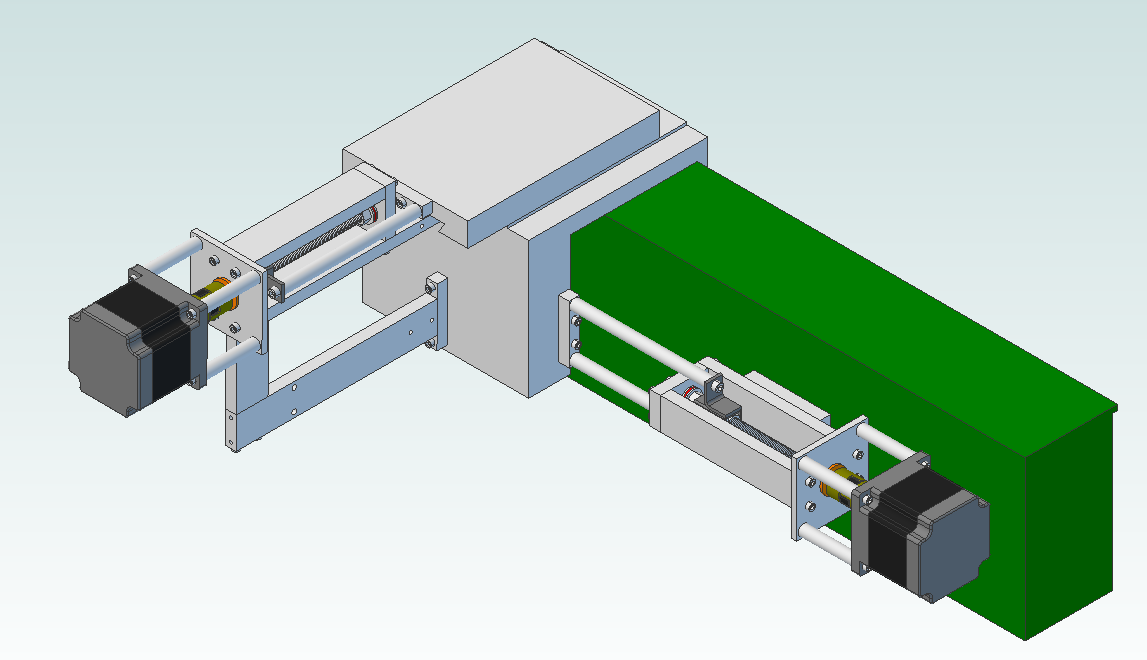
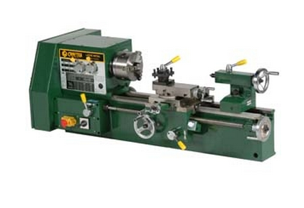
Hello everyone. My name is Mitch and I've been trying to cobble together a small machine shop for many years to make custom guitar parts of my own design. I think that my experience and interest fits in well here since I have always had a low budget and very little time to work on this kind of thing. I have read the discussion on building machine tools from scratch or to buy available equipment. In the end, it all depends on what you have available to you.My first assumption is that some sort of precision counts. This is especially true for CNC applications since a command to move a tool to a certain position should result in the tool moving to that position with some level of confidence. The tool should also return to that same position reliably each time it is asked to go to that position. Also, if we need to cut relatively hard materials, the thing holding the tool shouldn't flex so much as to affect the position of the tool when cutting.So far, for me, it has made the most sense to buy a relatively inexpensive milling machine and lathe from Busy Bee Tools. I work with small parts so the bench top units were fine.The next step was to convert the mill and the lathe to CNC. The simplest part is the controls: Old PC running Win XP or Linux, control software like EMC2 or Mach2, stepper drives connected via parallel port like Gecko drives or Xylotex, power supply, switches, wiring, fans and then connect the drives to suitably sized stepper motors such as Xylotex, Gecko, Kinetic Step, Motiontech etc.The hard part turned out to be taking my mill and lathe apart to fit anti-backlash nuts or ball screws and mounting the motors. The thing is that I needed the mill to modify parts to put the mill back together, what a pain! Lucky for me, a Roland PNC-3000 CNC mill came my way and solved the CNC mill problem so my focus turned to the lathe. Don't worry, the lathe part still applies to milling machines.So there I was, milling machine solved but starting to think about taking my lathe apart, uugh. Then I had an idea, likely not a new one, but new to me...Hmmm, I have everything that I need, computer, drives, motors, spindle, linear guides (built into the lathe), couldn't I just bolt on a linear actuator for the z and x axes and voila, cnc lathe?! Bolt on cnc conversion, no taking the thing apart, just attach something to it!! You could even upgrade the unit to say a ball screw without taking the lathe apart. Excitedly searching linear actuators, I found out that these things aren't cheap and one of the reasons is that they have built in linear guides. But I don't need guides, they're already on the machine.Thinking that I'm on to something, I created some CAD models for my modular "CNC Thrusters". I'm at the stage where I have most of the parts that I need (relatively inexpensive, ok tolerance design), just need time to put it together. Projects can take me years to complete but they always move forward. The CAD model and lathe the model was created for can be seen below or as attachments.Some of the parts are making their way onto GrabCAD and I am willing to share the entire design as things progress.Although the design that I have is better suited to small machines with say strokes of 12in., this could be very useful for the Multimachine (powering the x-y table) and CNC Circuit Mill projects.Let me know what you think, be honest, it could be a really bad idea!Take care,Mitch
 Attachments
cnc thruster.png 83K B2227L.png 111K -
8 Comments sorted by
-
So...would you be removing the manual lead screws that are already part of the lathe?
-
Right! I forgot to mention that part:). The cross slide screw would need to be removed. Take out the two screws and thread out of the nut. Reverse the operation to put it back in. The apron should already be free to move on the rack as long as the power feed is not engaged. Great question!
-
Journeyman machinist. I have seen and designed conversions, and this looks ok to me, but beware of chips getting into the ballscrews. You plan to remove the X leadscrew, I should think you would also remove the rack or crank plus the Z leadscrew or the half nut to prevent mistakes. Those ballscrews won't leave you wanting for speed.
-
Thanks for the feedback evenstevens. I hear you on the mistakes that could happen on the Z axis and the importance of protecting the screws. Any other major flaws that you can see with this concept? Is this worth pursuing or is this just another flavor on what's already been done or even been done better?
-
The preliminary model is now available on GrabCAD as Alibre and STEP.
 Attachments
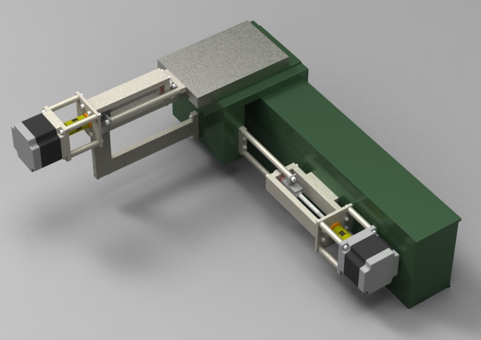
CNC lathe with thrusters.jpg 97K -
I think the most important aspect of any CNC machine has got to be the "trapping" which is to say the designs ability to restrict movement in the directions undesired while allowing movement in the directions desired. This does not clearly show that aspect. any chance you could show the device as a semi transparent design? I am working on a design that initially will be a cheap $300 kit that will allow a person to use off the shelf parts to complete and if they want to build a bigger machine they can either order more parts that go to the kit and expand the size of the rails, or they can use the kit and a simple vector line art program to design a similar machine kit and cut their own design that is similar to my design. the material is like a super hard sponge so it will hold tolerances under moderate vibrational levels such as a router or dremel cutting a part, while resisting deformation unlike metals and other solid materials that suffer from both deformation a little at a time (imagine tapping on a piece of metal with a hammer over a long time then increase the speed of the tap to 10's of 1000's of times a minute. this is what happens in a CNC machine made of steel or aluminum, where these are used to make the frame.) I am calling this vibrational creep since it is a form of creep caused by vibrations, and only during vibrational impacts.)
once I have reached my goal financially to allow for further design and development of other technologies, it will (along with G-code) be released as an open source file package. Hopefully then CNC machines will become truly available to everyone.
also to note I am including a packet of info that will grow hopefully with user input, on where to obtain supplies from salvage and reclaim them. I am using roller bearings in my design and have found that going to say thriftstores and buying up inline skates provides these are a lot less expense, and that most of the bearings are only dirty and not damaged, so flushing them with a simple tool I make with a piece of vinyl hose, a funnel, piece of threaded rod and two nuts, and a hand drill, brings them back to life. and any oil will work as long as it retards rust. I start with used motor oil to flush out the big debris, and then switch to new motor oil, to flush out the micro debris from the used oil. also I found that adding prolong to the oil or using used motor oil that had prolong added to it, leaves the bearings about as speedy as you can get, other than prolong treatment of brand new bearings heh heh,
another trick I have is tearing apart new dead LCD and older plasma TVs as around the screen there is usually a decent thickness aluminum angle that can be salvaged and used for brackets and reinforcement.
just as an example of what will be coming along with this kit that in a while will be opensource.
-
Hi morphtrust, I like your concepts, please keep me posted. I have some other ideas on a simple solution for a small lathe retrofit. Has anyone contemplated using suspended weights to eliminate backlash? If you want max 100lb of thrust, hang 100lb+ of weight off of a pulley in the cutting direction. The drive motor only needs to control the feed with the weight doing the heavy work while cutting then the motor does the work when the cutting load is off and needs to re-position. This would take lash out of the entire assembly including the nuts and thrust bearings.
-
I have not used counterbalancing for backlash but I do use a pulley and weight system to allow a smaller motor to move a fairly large head up and down to cut parts. works like a charm. speed is what it should be, and the wear on the lead nut and lead screw is diminished dramatically.

Howdy, Stranger!
It looks like you're new here. If you want to get involved, click one of these buttons!
Categories
- All Discussions1,013
- General Discussion895
- ↳ Introductions145
- ↳ GVCS Development43
- ↳ GVCS Replication14
- ↳ Similar Projects, Partnerships and Open Culture53
- ↳ In the News14
- ↳ Education15
- ↳ Food18
- ↳ Energy42
- ↳ Health2
- ↳ Sustainable Architecture21
- ↳ Transportation10
- ↳ Household6
- ↳ IT, Web Infrastructure110
- ↳ Shared Personal Notes1
- ↳ New Communities10
- ↳ Other Languages34
- Project Management4
- Proposal and Development Status10
- Organizational Development26
- ↳ Team Logs4
- ↳ OSE Core Team1
- ↳ OSE IT - Core Team2
- ↳ OSE Collaboration Platform - Core Team6
- ↳ Resource Development3
- GVCS Technical Development52
- ↳ Open Source Car10
- ↳ Open Source Tractor1
- ↳ Gasifier Burner1
- ↳ CNC Torch Table5
- ↳ Agricultural Microcombine4
- ↳ Dimensional Sawmill1
- ↳ Documentation and Instructionals18
- OSE Dev0
- ↳ Trucktor0
- ↳ Microtrac0
- ↳ CNC Router0
- ↳ CNC Torch Table0
- ↳ Bulldozer0
- ↳ Backhoe0
- ↳ Car0
- ↳ 3D Printer0
- ↳ 3D Printer Laser Diode0
- ↳ Tractor0
- ↳ Powercube0
- ↳ Brick Press Controller0
In this Discussion
- evenstevens March 2012
- Matt_Maier March 2012
- mgrdesign March 2012
- morphtrust April 2012
Loading