-
I figured I start a thread here for this project as it made
more sense than continuing to talk about it in the introductions forum.Overview: I am currently working on a solar foundry that
would melt small quantities of glass and metal for use in the personal fabrication
of small items, or for recycling and casting scrap metals. This system could
then be scaled up to accommodate larger quantities of material to be melted
down for both precious metal reclamation and scrapping, or for a small glass
working business.Design: The basic design is a Fresnel lens mounted in a
frame that is connected by supports to an attachment placed at the lenses focal
point. The lens frame is connected to two mast poles (one on either side of the
lens frame) where a motor controls the vertical orientation of the frame. The
masts are attached to supports which are in turn attached to a rotating
platform where a motor controls the stands horizontal orientation.The crucible design is spherical at the moment. This is
mainly because the crucible will be outside of a furnace in contrast to the
normal setup where the crucible is inside the furnace. It will have to be
highly insulated to keep as much heat inside of it as possible. It will be made
out of ceramic most likely, although it could be made from soapstone if used
for melting metals with low melting points.I am currently in the design phase working out the sizes or
various components and parts. The main construction will begin after I get a
Fresnel lens of sufficient size. For the time being I will be working on a
scale model of the full size stand. Ill keep this thread up to date with what I'm
doing as well as posting drawing, pictures and videos.I'm going to try and learn to use sketch-up or some other
free CAD in the future, but for now Ill
just stick with the pencil & paper, and good old paint program.Thank you to dorkmo for drawing the basic design in sketchup!
http://sketchup.google.com/3dwarehouse/details?mid=5eec7c1a68191fdfb38804396e417a9b
Attachments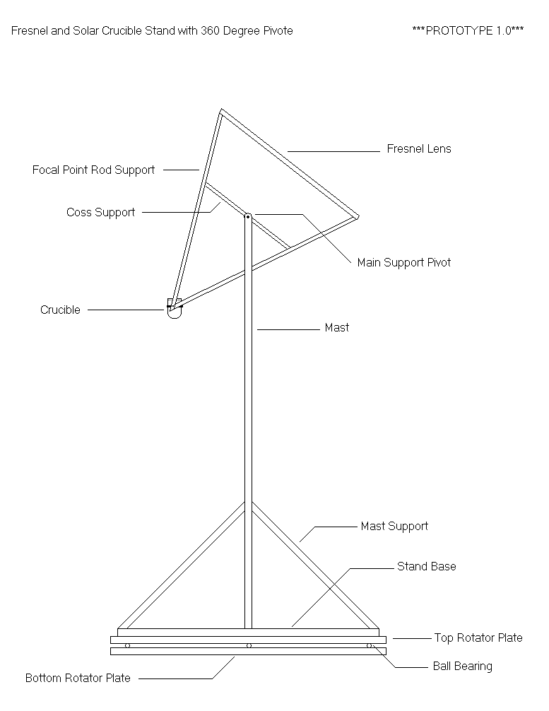
Fresnel-Crucible stand side profile1.PNG 28K 
Crucible Mounting Arm1.PNG 21K 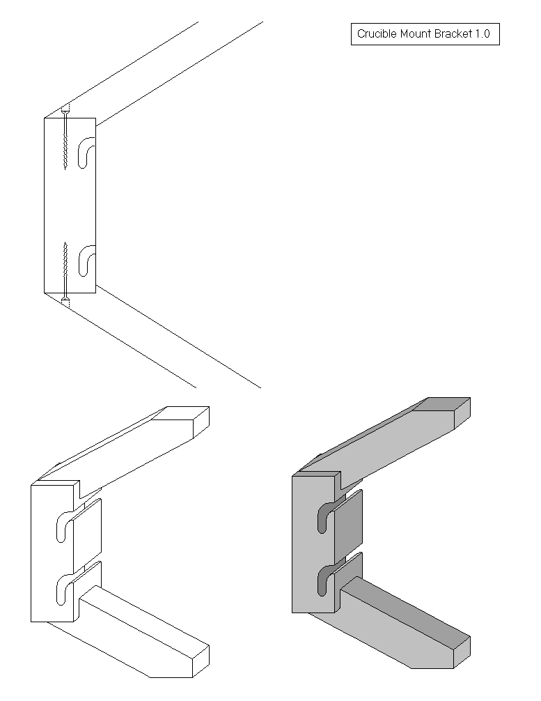
Crucible mount attachment1.PNG 26K 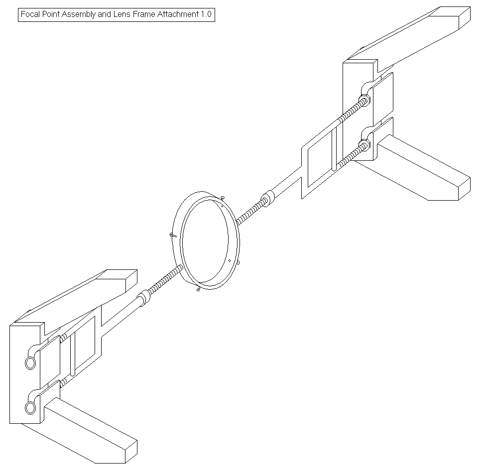
Crucible Mount Arm and attachment1.PNG 34K -
8 Comments sorted by
-
Call me a physicist, but I'd like to see calculations on the static heat level of your insulated crucible given expected heat input from the sun vs. the loss through insulation and the heat input port.The output of those equations will dictate the required size of the lens per sun intensity available.Without those equations, we don't even know if that's more than enough of not nearly enough.
-
@DavidIAm - In all honesty, I wouldn't know where to begin figuring out those equations, or even which ones to use. In any case, I do not yet have a crucible to run the math on. I have an idea for the insulating material that could be applied to the outside of a spherical crucible but I do not know many of its physical specs. I know its melting point is 1800C and has a thermal conductivity of 0.1 W / m / Deg. C. Here is a promo someone did for it:
I am trying to find out more information about it.
-
I'm very interested in a larger scale multi-purpose solar furnace. The idea is to have a general purpose heat source for: cement making, metal foundry, heating to forging temperature for metals, glass making, etc It would consist of a field of heliostats (mirrors) and a stationary target building. The building has a safety wall facing the mirrors, with an opening for light to enter, and an insulated target chamber behind the opening. Depending what task you are doing, you change out what goes into the target chamber and how many mirrors you focus on the target. You can start out with only some of the mirrors built, and add more over time. For extra high heat, or on cloudy days, you can have a gas burner or electric heater in the target chamber. You have a lid or door to the chamber to access whatever you are heating. This is tied to a shutter that closes the sunlight opening, so you are not blinded when you handle whatever you were heating.
Besides the safety wall protecting you from concentrated sunlight, the other reason to work indoors is to judge the temperature of the heat. A solar furnace necessarily operates on a sunny day, and from experience doing blacksmithing, you need a shaded place to work to see the color the metal is glowing so you know what temperature it is. To know what energy input you need, look up the Stephan-Boltzmann law. Generally, any object will radiate energy per area as the 4th power of the Kelvin temperature times some constants: The Stephan-Boltzman constant, and the emissivity. A black body has an emissivity of 1.00, and other materials you look it up. Your crucible will be trying to radiate energy out by that formula. So the best arrangement is to have an insulated chamber with a small opening that you feed in sunlight. The hot crucible will try to radiate in all directions, but only the radiation in the direction of the opening gets out. The rest falls on the chamber walls, which radiate back.
-
Ive been going over the math for melting glass and the crucible. I honestly am not 100% sure about it, as I mostly pieced it together from various how-to's and online calculators. But here is what I have so far.
Total energy required to heat and melt 1cm3 of SiO2 (25C to 1700C) = 3 534.99 Joules
The energy required to do this over different times:
30sec: 117.833 Watts, 60sec: 58.916 Watts, 300sec: 11.783 Watts, 600sec: 5.891 Watts, 1800sec: 1.963 Watts
Regarding the potential crucible. The ceramic composite has a heat conductivity of 0.1 W / m / C. Assuming it is made entirely of this material with a 3cm thick wall it should have a heat transfer rate of 0.4 calorie/cm2 -s. This is given that there is a 1675C temperature differential between the inside of the crucible and the outside ambient air temperature of 25C.
I would need someone to confirm this who is more sure of themselves in math than I. My head hurts now hehe. I'm more inclined to just build something and test it through trial and error.
-
@Metz - I have seen the videos of the solar sintering project. It is very inspiring, as is the solar laser cutter. I have been tossing around the idea of playing with sintering as well, albeit in a less technical way. Perhaps a manual or mechanical system over a computerized one.
An update on the foundry. I have most of the materials for the model now and am starting to build it. I should have my first large Fresnel lens in a couple of days. I'm waiting on the solar cells and gear boxes to arrive so I can start on the solar tracking system. I also found some ceramic spheres at the dollar store of all places and am going to try to re-purpose them for small crucibles. It is fortunate that they are so cheap as I can test various insulating methodes cheaply and test them to destruction if necessary.
-
Another update.
I have the model mostly done, I'm now focused on wiring it together. The wiring is very simple, just four solar cells wired to two Tamiya Worm Gear gear boxes. I bought 10 tabbed cells and thought I would use them, but I am having a hard time getting them wired correctly. All the instructions I have found have been for soldering them together, whereas I need four individual cells wired separately. When My camera is done charging Ill post a photo.
-
OK, here are some photos of the model. The structure has been put together using wooden pins so that I could assemble the whole thing and discover any errors that would have to be corrected without rebuilding the whole thing. I then glued all the parts sparingly. The wooden "Lazy Susan" style base has about 60 1.6mm marbles acting as a bearing. It works fairly well but is a little noisy and my lack of precision routing tools means it is not the smoothest turning motion that one could get. The motors for both the base and the lens frame have plenty of power running off of one AA battery. I may try to get lower rpm motors though as even with the 336:1 gear ratio it is still jerking around a bit too much.
In the full sized version of this I'm hoping to have a gear ratio that would allow for 180 degrees of motion in about five minutes, or a gear ratio of about 10 000:1 with a 1000rpm motor. I figure that would be more than what is needed to track the sun or move it back into alignment should a cloud pass over.
Attachments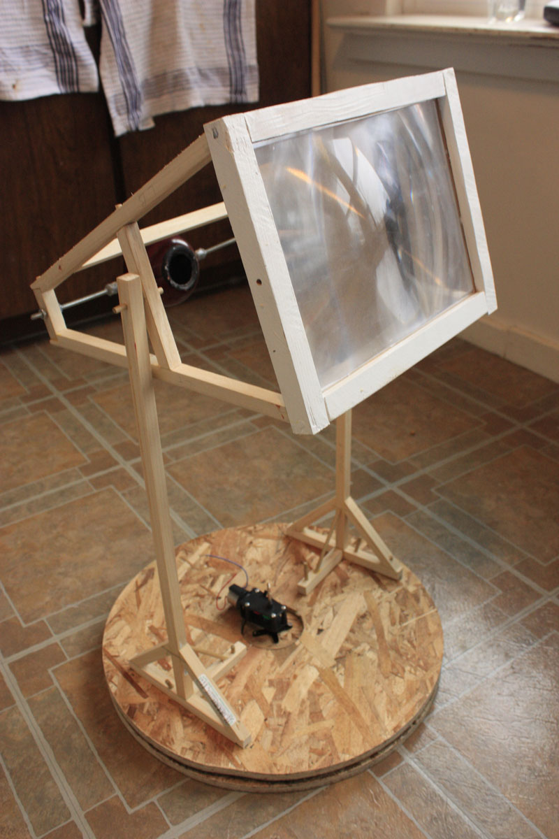
_MG_4358002.jpg 176K 
_MG_4360004.jpg 116K 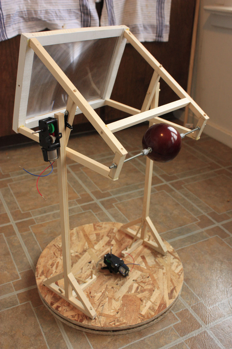
_MG_4361005.jpg 192K 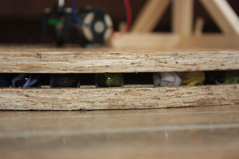
_MG_4363006.jpg 80K 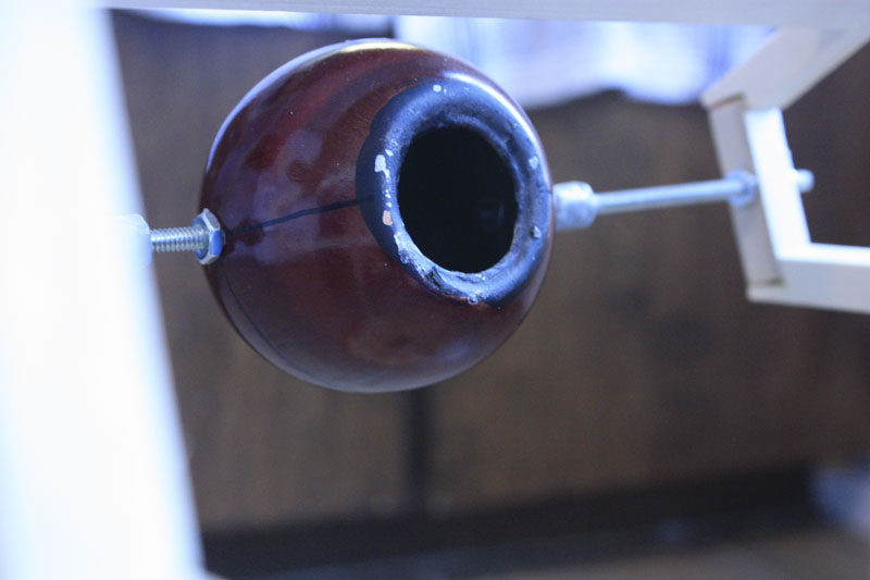
_MG_4353001.jpg 63K


Howdy, Stranger!
It looks like you're new here. If you want to get involved, click one of these buttons!
Categories
- All Discussions1,013
- General Discussion895
- ↳ Introductions145
- ↳ GVCS Development43
- ↳ GVCS Replication14
- ↳ Similar Projects, Partnerships and Open Culture53
- ↳ In the News14
- ↳ Education15
- ↳ Food18
- ↳ Energy42
- ↳ Health2
- ↳ Sustainable Architecture21
- ↳ Transportation10
- ↳ Household6
- ↳ IT, Web Infrastructure110
- ↳ Shared Personal Notes1
- ↳ New Communities10
- ↳ Other Languages34
- Project Management4
- Proposal and Development Status10
- Organizational Development26
- ↳ Team Logs4
- ↳ OSE Core Team1
- ↳ OSE IT - Core Team2
- ↳ OSE Collaboration Platform - Core Team6
- ↳ Resource Development3
- GVCS Technical Development52
- ↳ Open Source Car10
- ↳ Open Source Tractor1
- ↳ Gasifier Burner1
- ↳ CNC Torch Table5
- ↳ Agricultural Microcombine4
- ↳ Dimensional Sawmill1
- ↳ Documentation and Instructionals18
- OSE Dev0
- ↳ Trucktor0
- ↳ Microtrac0
- ↳ CNC Router0
- ↳ CNC Torch Table0
- ↳ Bulldozer0
- ↳ Backhoe0
- ↳ Car0
- ↳ 3D Printer0
- ↳ 3D Printer Laser Diode0
- ↳ Tractor0
- ↳ Powercube0
- ↳ Brick Press Controller0
In this Discussion
- Danial January 2012
- danielravennest December 2011
- DavidIAm December 2011
- Metz December 2011