Visit the forum instructions to learn how to post to the forum, enable email notifications, subscribe to a category to receive emails when there are new discussions (like a mailing list), bookmark discussions and to see other tips to get the most out of our forum!
Steam Engine
-
In recent weeks, Marcin and I have re-visited the earlier efforts to develop an open source steam engine. We've updated the design based on new information. I've created a number of diagrams that illustrate the design concepts and we are just about read to open up the new design for review. I'd like to establish this space for discussion related to the steam engine project. Feel free to add sub-topics focused on specific problems or challenges.
-
12 Comments sorted by
-
I have been making notes on the steam engine too. Here are my notes, essentially unedited so I know they are full of typos etc, that's because of the subsize keyboard going on here...
I know it seems like I may not be focused on the particular implementation you have in mind, but I have read the wiki pages and I think it is important to consider all options, then pick the best one, because you don't really know which is the best until then.
Again I have to split it up, my comments after having another look at the steam engine pages on the wiki will be last
the science called tribology helps tell us how a low maintenance steam engine might be made. The lubricant film thicknesses of water at the temperatures involved would need to be worked out. It depends largely on the dynamic velocity, surface gets coated with lube, then part presses against it and the fluid flows away with exponentialy decreasing volume/second rate.
A steam engine can be run "dry" or "wet", in which some water does not or does condense in the engine. I read the wiki page on steam engines, and clicking and reading through wikipedia is also helpful but only gets you so far as information like efficiencies of real world engines is lacking.
I'm pretty sure regenerative engines have the advantage of being very wet, and although for biomass there is little or no need for the effieciency improvements of the regenerator, this might be worthwhile. Wet is bad for turbines as it damages the blades, but for other expanders it may help lubricate things.
might be dual use for organic rankine? For whatever reason these are what seems to be used at the ~377 temp that is anticipated from the solar collectors. In accordance with systems engineering principles it would be a good idea to produce simulator models to estimate the performance of the collectors, since the performance of the system overall is intricately linked. It's lame but it's convenient and easy for others to interpret modify and understand too: Just making a time-step simulation in Calc and perhaps using the genetic algorithm solver plugin might be one way to do this. I have used this in excel with Evolver plugin (expensive but I have a copy) which I could do if the calc plugin is too... beta. Then the output that various engine designs would produce with this input can be estimated to choose the most suitable engine.
If the engine is biomass fired this isn't a problem though, run it at the highest temperatures practical (actually see calculations on the turbine practicality below).
I might make more sense to get rid of the steam generator and use hot air as the transfer medium for biomass at least since the combustion gas has to be blown around anyway. most steam engines run at 500 to 550 degrees.
Once the lubricating film thicknesses are worked out, a bearing could be selected for a turbine, since viscous fluid losses of ball and roller bearings go up with I think the cube of rotational speed they may end up impractical, fluid bearing with water can be used maybe, but decide on a bearing and then determine accuracy needed to have acceptable loading on the turbine due to imbalance at the speeds involved. A small impulse turbine may have to turn at very high rpm for the rim speed to be suitable ( half the speed of sound?) and centrifugal force is proportional to rpm squared so that might be a problem, compute it a centrifugal turbine any better? Also material strenght has to be sufficient at whatevery rpm, need to avoud any resonances etc.
ORC engines wikipedia says turn the turbine more slowly for some reason, so can turn the enerator more efficiently (and probably other stuff too).
Sealing shafts:
, capiliary forces = higher when opening is smaler, phenomenon used in the water intrusion test and in reverse as the bubble point test for filters. But a 0.22 micron hole requires only 50 psi or so and once the water wets the surface on the other side of the hole the effect dissappears. The crankchaft area might be relativel low pressure though. However if the opening becomes whetted the effect can be ruined.
ideas: see a "gland"
http://en.wikipedia.org/wiki/Labyrinth_seal what pressures are they good to? But looks like they only work while the engine is running, although pressure could be deliberately let down to avoind problems when stopping the engine. Says they don't wear out.
at some efficiency cost, heat could be allowed to escape from the crankshaft area thus keeping pressure low maybe even lower than condensate side, though some water would get over there it could be pumped back as condensate. note: vent the crakshaft to low pressure side
use a series of discs wit hholes in the center, mounted o na shaft, spaced part then, interleaved with other discs that are attached to the housing, the goalt o make the the flow path as long as possible.
how is it done in submarines? Industrial turbines? Hydraulic pumps and motors?
some types of hydraulic motor might be modified to work as a steam engine or orc expander, have to account for reduced strength at higher temps though it might work, depends on compression ratio too.
What about brayton cycle with liquid water or something? or High temp hydraulic oil can go to 400 degrees, brayton cycle with regenerator and oil? would have to be a very small expansion ratio though, there area some companies looking at water expansion motors for solar thermal esp. nighttime storage, organic rankine can be done with a liquid ring pump
night storage: sand or gravel bed could be used like a regenerator, helping to preserve the temperature (grade) of the heat which would be important for solar. Molten salt might not be that hard or expensive, might want to have multiple stages with different salts that melt at different temperatures again to preserve grade and allow storage at whatever grade is available from the collector. Remember hearing KCl might do for solar thermal, puttin heat in is easy, getting it out is a littl harder because the salt freezes to the heat transfer surface. Fill barrel with metal tubing?
ensure lubricant is present during startup or very soon after of the engine somehow or substantial wear may occur, or anti wear coatings might be needed for long life, maybe not, but this is a known problem for the hydrostatic bearings on crankshafts and foil bearings.
Expander options:
piston obviously, v 8 or radial or wobble plate
Al
-
rotary screw compressor - this seems interesting, basically like a roots blower but with the vase profiles extended in 3 dimensions and twisted. There is the so called "infinity turbine" organic rankine engine that uses this for industiral heat recovery. The vanes in a roots blower can alctually be a wide variety of shapes, imagine 2 discs that are overlapping to a greater or lesser degree. Imagine a line drawn between the centers of the 2 disks. Imagine a point along this line which is in the area where the 2 disks overlap. Now, imagine both disks start turning in synchrony, and turn one full revolution, and move the point back and forth to the left and right in whatever desired motion while removing all the material from the right disc which is to the left of the point, and all the material from the left disk which is to the right of the point during the rotation. After a full rotation you have a set of intermeshing vanes. They can be gears like in a gear pump if you wish. Obviously different shapes are suitable for different purposes, but it shows the vanes can be whatever whatever shape you want so long as they are both the same and are symmetrical along at least one axis. Another cool impication of this is that you can almost re-machine the screws after they wear out and make the expander slightly different but still perfectly functional, with the exception of the one point at the widest part of the vanes (the tip) and where this part meets the other vane, which if you remove any material from would make it impossible to mesh the vanes perfectly at that point of the rotational cycle. However that is only one instantaneous point during the rotation so maybe that would not be a significant problem. However the vanes could be moved a smidged closer together during the refit process. But then you can remachine a cylinder bore for a (new) piston too.
one problem with a screw compressore might be that the seal between the high pressure side and the lower pressure side is a line, unlike in a piston where it is an area, the area between the piston and the cylinder wall. That might result in more steam leaking past the seal, reducing efficiency.
reaction or impulse turbine - impulse allows the bearings to be fluid bearings, keeps heat away from the bearings a bit, reaction means more even loading on blades I woul d think. Question: how accurately does the turbine need to be machined?
x, y vector, same magnitude, ys all cancel out, only x remains, average height of curve x=sqrt(r^2-y^2) area divided by width area is (pi/4) so the force is pi/4 whatever it would be if all the mass were on a point on the rim [edit: I was thinking of the worst case scenario, in which a perfectly in-round turbine rotor assembly had a uniform extra 3 microns thickness on the left or right half of the outer side) , so if machined to within 3 microns round density of steel multiplied by 3 microns by width of turbine cross section suppose 2 cm, 0.25 m radius so 785 cm long strip 0.0003 cm by and 2 cm 0.471 cubic cm 3.69264 grams cent acceleration is (v^2/r) so for 222 m/s (800 kph) and 0.25 meters radius 12321 m/s^2 so 45.5 newtons, edit: using the calculations regarding the nozzle exit velocity below it would be about 521.8 newtons darn, and that is only thinking in 2d, if the errors along the z axis are considered the amount of mass goes up substantially. The so called de laval turbine uses a flexible shaft so that the z axis errors cancel themelves out more or less, but this might agravate the effect of x,y errors.
If a milling machine is used to produce the blades then the 3 micron out of round figure no longer applies though. High rpms at low torque would make magnetic coupling out of th case more practical, the problem being eddy currents, the magnetic coupler housing would have to be plastic or ceramic or something
However from what I have read hydrostatic bearings are capable of withstanding very high forces, like in a piston engine the force on the crankshaft at high RPM is very high, not from the combustion but because the velocity of the piston and it's ensuing mass needs to be reversed each cycle. I have seen it quoted in the 10,000 pound range for racing engines crankshafts so we should be fine.
rpm would be 8500 rpm or so, that's not that bad is it?
okay from the equation at the de laval nozzle wikpedia page, calculating the velocity of the steam
pe/p assume is worst case 1/1000, then pe/p^(k-1)/k = 0.2
then 1-(pe/p)^(k-1)/k = 0.8
t*r/m=332580
2k/k-1 = 8.6
1512.6 m/s
for impulse only half that is needed still 756 m/s
if it was to 20 microns with a milling machine comesurately higher
from the de laval nozzle page equation
for pentane
5 carbon plus 12 H so 72 total vs 20 for h20 so would be 398 still plus pentane might not be stable at 500 deg c
if used steam and multi staged it with 3 stages then the pe/p might be 1/10 at each stage so pe/p^(k-1)/k=0.584 so 1-0.584=0.416 an and velocity might be 550 m/s or so
So an impulse turbine might make sense, depending on the details of how hard it is to do that machining. Actually come to think of it it migh tbe possible to rather doing acurate machining, just be careful about where the axle goes through the turbine, and at what angle (to reduce z axis imbalance). As long as it is in the center of gravity the amchining does not have to be super accurate, does it? how important are aerodynamics? I wouldn't think they would be a big deal if 25 micron could be acheived yeah? a balancing machine could be made perhaps to get the hole in just he right place, or maybe it could eb balanced after manufacture relatively easily since we are taking about several grams of material. And again the bearings are capable of standing high forces. The same turbine could maybe be reused with an organic fluid and a magnetic coupler for the solar thermal, ensuring very long lasting and pretty good efficiency.
if the turbine were mounted on a long vertical shaft that was a bit flexible would it be self stabilizing at some speeds? would have a resonant wobble speed/frequency still
"In the divergent nozzle the whole expansion of the steam is carried out. The steam at the mouth of the nozzle has the same pressure as the exhaust. In other-words the steam has its energy completely transformed into mass and velocity by the time it comes into contact with the buckets. This brings up another feature of this turbine, and that is that no parts with the exception of the nozzles, are subject to steam pressure." god news for the turbine houseing, if there is only a small amount of water permitted at any time then maybe it would be safe to use relatively thin walls also less distortion http://chestofbooks.com/crafts/popular-mechanics/Amateur-Work-5/The-Steam-Turbine.html
material strength for turbine:
strength of steel at thi speed: suppose a square rod, coudl find integral of the centrifugal force function but supposing the whole weight of the rod is a the tip, 1 cm square, 0.25 m long, 756 m/s iron is 7 g/ml so that is 0.250*7= 1.750 then 756^2/0.25= 2286144 so 4,000,752 newtons, strength of high strenght steel is 760 mpa so 76kilonewtons over 1 square cm . hm darn.
at 398 m/s 1,108,828 newtons. So clearly really a lot of multistaging is needed for a small turbine like this, or heavier workign fluid or smaller temperature differential or something -
else if it is to be doable. Also maybe a material like titanium with it's higher strength to weight ratio. Piano wire is 2.2 GPa according to wikipedia. It might still be doable, also lookup "creep" material can't really be used above certain fraction of melting point, also strenght goes down as temp goes up derating. Working at lower than optimal turbine speeds also may be acceptable while still givng good efficiency and the advantages like asingle moving part. Multistaging too. Taking a variety of engineering options it might still be doable.
closed brayton cycle with foils bearings?IIRC used in some power plants no, see material strength above, hey what about with a very heavy gas like sulfur hexafloride? molar mass is 146, 8 times that of water, and at the 3200 psi pressure we are talking about, it achieves a density of 1.28 kg/liter, more than water, although obvious problem with brayton cycle is transferring large volume of fluid back to the hot side
if producing electricity only free piston stirling may be worth consideration but the killer may be the aditional delevopment effort of 2 engines vs 1. They can be completely maintenance free, lasting 20 years or more. There have been hydrogen charged engines but I don't know about FPSE ones, if the spring were embrittled by the h2 that could be a problem. What about neon or argon? any better than N2? Can get those from the air easily enough at some energy cost. Could the springs be elastomeric and located ina cold area of the enigne (some silicone elastomers are good to 320 c or so) these companies are using helium which is not good, but see sunpower, infinia (used to be called stirling tech, there is still one but they are different people), enatech.
honda produces a maintenance free internal combustion engine for cogeneration they call the freewatt. How do they do it? Ceramic parts?
http://www.rosler.com/english/vibratory-finishing/rem-process.html need patents to duplicate
ferrofludib bearings? no need probably since we have the water but interesting for e.g. a mill
http://machinedesign.com/article/the-attraction-of-ferrofluid-bearings-1103 you can make your own nanoparticles of iron have seen it done one chemistry forums
wikipedia article at the end has an example of bearings in use for more than 88 years with no parts replaced
"conical or rocking modes"? adnd half frequency whirl
foil bearings says loading 1 pound for one square inch bearing surface per inch diameter per 1000 rpm so maybe but pushing it
http://mysite.du.edu/~jcalvert/tech/fluids/turbine.htm
microturbine interesting http://www.seminarprojects.com/Thread-microturbine-full-report suffers the same problem as us, the need to be small increases rpm needed.
fluid bearing http://www.epi-eng.com/piston_engine_technology/engine_bearings.htm notes that bearings in an IC engine support extremely high loads, the main bearing on the housing must too, need to find out in more detail and calculate viscous losses at high rpms we are talking about.
"quasiturbine" is interesting, and since the hyrosstatic bearings are capable of standing very high forces maybe it could be designed so that all the sliding parts would last well if accurately machined and polished.
Wankel engine. not investigated yet
All
scroll type: interesting but what advantage ofver piston? Co rotating scroll expander is interesting, described on wikipedia page
some types of gear pump , the "star rotor" intresting how these old expanders/compressore are being taken out of the books and put to use in ORC engines. what is the drive mechanism they use? they say it can only handle compression ratio of 6 to 1 which is nowhere near engouh , might be okay for a different cycle though they have a thing about a braytnon engin e with it http://www.eng-tips.com/viewthread.cfm?qid=80554
consodered an drejected, gear pump,, that ecentric pump
"claw compressor" interesting much like piston engine but no crankshaft
another scre example http://www.wipo.int/pctdb/en/wo.jsp?wo=2004025107&IA=US2003027408&DISPLAY=DESC
"rolling piston"?
single (globoid) screw
guided roto http://grcompressor.com/#section2
that one used for sewage that used a universal joint and rubber seals
for electricity acoustic stirling engines are interesting and could be very cheap
also maybe air motors wold be ready to go
-
- economizer on the output needs to have the flow reversed periodically to have any function, what is it doing there? Where is the heat for the air preheat coming from exactly? Not clear from the diagram.
- the flat plate exchanger is at the same pressure as the high side? It would not stand any decent pressure surely.
You can get diaphragm pumps at 3200 psi? that is what the cyclone runs at (same as a hydraulic piston, could use soem types of hydraulic motor as the expander, or an air motor)
could use only a small amount of water, greatly reduces safety problem, cyclone seems to do this
if this were only for eletricity there may be better options than steam, FPSE in particular
- carbon monoxide nasty stuff
- does nto match the way I have read efficient wood gas generators normally work, unfortunately they are also not that cheap in themselves, some web pages trumpeting breakthrough prices at $1/watt just for the generator
funny sort of heat exchanger you go there, what about a ube in tube instead? Filling a tube with sand allows the tube to be bent however without kinking.
maybe do things in a more schematic or symbolic way too, working down from high level design to progressively lower, rather than this combo of symbolic and representative of the anticipated final form,
preventing corrosion:
is water itsself corrosive? Maybe at high temps? I don't think so, because old steam or hot water heating systems don't corrode from the inside out, it is only when O2 gets in that you have a problem. In hydronic residential stems they use metal parts, but they must use oxygen-barrier tubing to prevent corrosion or the parts are quickly destroyed Likewise steam turbines seem to not have a problem though threy could be a corrosion resistant material I dunno. This requires the engine be sealed reasonably well though, to prevent ingress maybe if it was all positive pressure at all times the makeup water required due to leaking could be deooxygenated some how (nasa uses a vacuum pump plus a hollow fiber module to degas water on the space startion sometimes, the relevant gases diffuse across the module plastic barrier but water vapor or liquid water does not very well, silicone modules might do fine just needs a very small one, polyethylene might be okay too)
Stainless steel might not be such an unreasonable option from a cost standpoint all things considered. The material cost is going to presumably ne dwarfed by the other costs. The oxide passivatio layer may disappear under low oxygen conditions (the commo nexample being underwater boat hulls) though so if water itsself is corrosive it might not help.
-
- precision machining is highly useful anyway for a wide variety of purposes so I'm not sure if it makes sense to avoid it. If it is not yet available maybe it makes sense to focus there instead as it is a basic need for good machinery.
- how do they do the electronic valves in an ice? They are very fast , cyclone use a cam and needle valve system http://www.freepatentsonline.com/7784280.pdf, yes after looking at the patents looks like an electronic needle valve might be a good idea if control of compression ratio is desired, the engine has a cam on the crankchaft controlling the needle valves, how did they ge tthe mechanical motion from the low pressure side to the high pressure without steam leakage? Just sliding seals I guess Maybe metal flexure beryllium copper etc. coul dbe a "torsion tube " flexure , use finite element analysis , might be a good reason righ there for electronic valve in the future although variable ratio only really needed for variable temp input which is not applicable to combustion input
- could have a cam in the piston head to prevent reversal of rotation for hydraulics and shaft power needs, cam in on the shaft for the piston head bushing, the nrod riding on the cam goes through the piston head, at the right cycle angle it is higher than the piston head, it rises slightly after top dead center
maybe the rest of the systems could be designed so that it doesn't matter if it runs backwards or forwards easy for electric , or you could have another mechanism to ensure forward which was mounted on the crankshaft and forced the system to not come to rest in the wrong position, but rather in just the right place in the cycle (rolamite?) start thus eliminating the cams there would always be a small risk of the system going backwards though
- since the timing does not change very much from injection to injection a valve that was like a ball valve that rotated coudl eb used, brushless motor back emf commutated has to be free of solder etc though could make own with layered silicone steel and welding
- ball bearing with a hole drilled in th emiddle or roller bearing even better for the valve
- integrate the boiler into the engine and just use hot air as the transfer medium for biomass burning since there is temperature to spare but for solar simply moutn the engine so light shines thgouh aperture into the absorber, coated with ante emission stuff, large surface area of tubes does not matter remember only aperture is like a light bulb, the radiation coming out the aperture cant be increased after a certain surface area is already emitting
- to increase grade and therefor efficiencyesp at low sunlight levels use still air, put a glass window and insulation to prevent convection afay from the collector thermal gradient is oriented so there is no convection
- wonder if you could use the equivalent of water hammer to get even higher pressures in the piston than in the boiler,
http://www.astromet.com/macor.htm might be useful for the valve
- use the generator in reverse for self starting
- for high pressures use small diameter tube, the ratio of wall thickness to tube diameter determines pressure resistance, so this is and easy and relatively safe way to make the high pressure exchanger, ask a mechanical engineer if you don't nelieve me, this is done in the cyclone
idea for biomall burner :
see attachment Basically you have a counterflow heat exchanger, and drop the fuel down the tower, potentially through a tube which is embedded in the exchagner and is part of it. It hits the slide at the bottom, moveing slightly laterally to land on the burn pan ro grate C. After burnign to ashes either the ash falls through grate a grate or maybe is just blown off the pan, anding in ash drawer D which can be quite large if desired
Assume wood is all cellulose, how much air is needed to combust wood?
co2 and water from 6 o2 per 72 +10+ 80 162 total so 22 liters per mole so 110 liters per mole air so 27 grams cellulose per 110 liters air
How much energy do you get by combusting a liter of air with wood?
14 mj per kg for wood so 0.378 mj per 110 liters air or 0.00343 mj per liter of air 3.43 kj
so 1 liter per second is 3.43 kw.
Is drawing o2 in practical with convection alone?
Suppose exit temp is 60 deg c, ideal gas law suppose 298 degrees ambient input, 35 degree temp differential across exchanger then very roughly density dif is 333/289 = 1.15 at cold end, hot end 948/913=1.038 or 4% so assume 10% then that is weight of column which is 1.27 kg *9.8*0.1/1 sq meter = 1.244 pascals difference in weight of the columns per meter of height, so the flow rate would be what, ignoring viscous issues assume a 5 by 5 cm hole 25 square cm the force is 1.244 pascals by 1.5 meters high so 1.866 pa, on 1.27 *1.5 =1.9 kg so energy is 1.866*1.5 = 2.8 joules velocity e=mv^2/2 so 1.71 meters per second, by 25 sq centimeters is 4.28 liters per second so convetion sound be enough for a lot or purposes, the tower can be taller and the exchanger can be much much wider if you wish
What should the temp drop be?
Ignoring the conductivity of the metal which is plenty IIRC, a rule of thumb for natural air convection from a vertical surface is 25 watts per degree per sq meter, that;s each side so 12.5 total so if the temp diff is 35 degrees and there's 1 liter per second and 3.43 kW that's but the convection rate at room temperature .. hm. Well the convection rate at the heat exchanger would be probably a lot less due to the lower density differential produced per degree, but assuming it is the 10 percent figure above, have 3.43 kW and 35 degrees, how many sq meters, about 4 so should be fine would be about 4/1.5=2.67 wide sheetso wihth 26 folds each 0.4 cm wide might do. better way to find the heat loss value from a metal surface subject to laminar flow of air?
oops density of air is 1.3 1.27 is the heat capacy well whatever
Wood is usually no more than 5% ash, what is the density of the ash, so we can tell how long it is between emptyings?
How fast does the air need to convect to the engine and back again? Assume a 100 degree temperature differential, fo3 3.4 kw it would be
1.27 j/degk*gram so 127 j/gram so 1.65 kj per cubic meter oh hm. Well maybe the engine will need to have a blower to suck gas in and pass it over it's exchanger
Is the lowest practical efficient combustion temperature in the acceptable range for input to the engine?
I think so if not the temperature can be deliberately downgraded without loss of heat using a crappy intermediate heat exchanger between the engine's exchanger and the combustor. . The engine components can only go to 30% of their melting point before structural issues and creep arise, but the crappy exchanger has no force on it so it can be operated at plenty high temperatures on the hot side if made of stainless steel.
- the design of the combustor proper in the attached fig needs to bea adjusted, with a secondary combustor box as usen in many wood stoves, to achieve the most efficient combustion and avoid creosote in the exchanger and chimney fire, or a very small blower could be used and the heat exchanger turned sideways to prevent convection and a drawer like method of getting fuel into the chamber coudl be used but that seems like a waste
how to power the auger? Maybe a small curie effec theat engine coul dbe used somehow. just as a handy method, otherwise connect to crankshaft, motors etc.
-
advantages:
the biomass hopper can be very large, eliminating the need for frequent refuelings
the counterflow heat exchanger can improve efficiency
only combusting as much as is needed
no toxic carbon monoxide - what happens if the flame went out on the gassifier's babington burner? A lot of CO released. Therefore needs thermocouple or other sensors plus ignition circuitry to relight it or shutdown automatically to avoid risk of gassing someone.
fewr pumps and valves
combustion chamber is small, inherently safer and easier to shut down/start up
Smaller unit may be easier to insulate and/or cheaper due to less materials.
Steam engine is more multipurpose and easier to connect to other heat sources without risk of bending pipes etc. when moving it around.
Attachments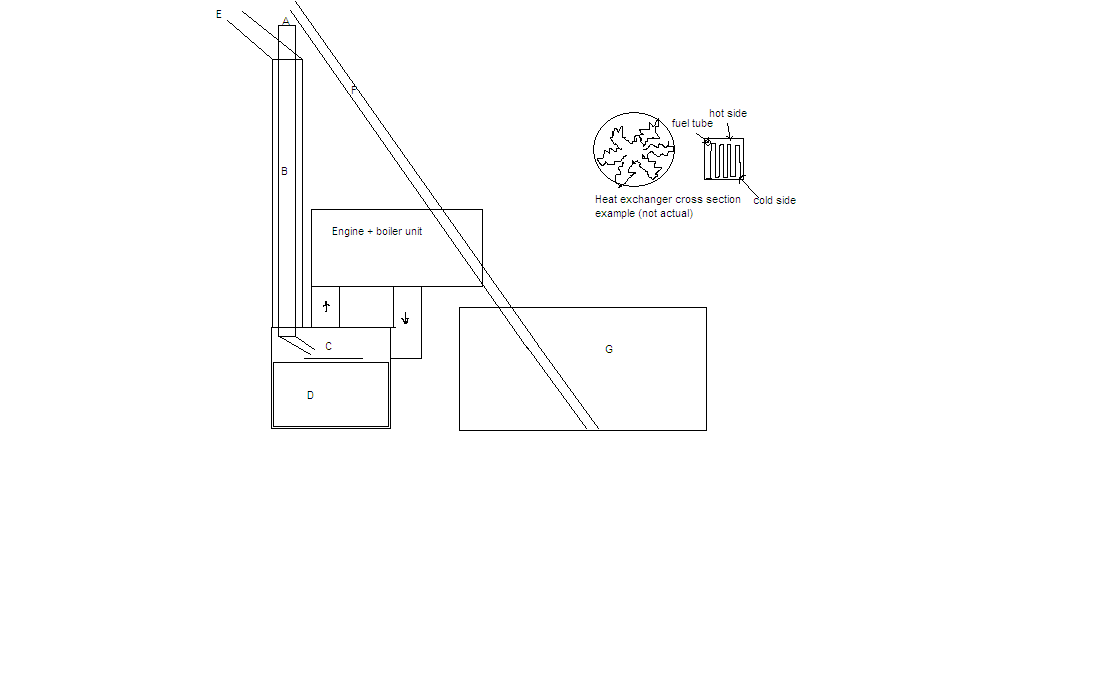
biomass for steamburnber.PNG 24K -
@gregor
I apologize for missing your extensive response to my original post. Truthfully, I wasn't tracking the forum after it was created. I am attempting to do better about tracking the forums and being involved in them.
Regarding your extensive notes above. There are many interesting ideas and possibilities that bear exploration - far more than I have time to do them full justice. However, I have copied your notes to the wiki at http://opensourceecology.org/wiki/Steam_Engine_Design/Gregor. They are (at best) rather stream-of-conscious. While I appreciate that this is often a good way to get a lot of things into writing rapidly, it makes it very difficult to read. I have therefore attempted to break out the material into sections of some kind. I apologize again if the organization is not according to your original thoughts and invite you to improve the organization by editing the wiki page.
Recently, I complete the first pass at a set of 2D technical documents that describe all of the parts in the currently proposed design. In the process of doing them, several problems and possible improvements were discovered. I will be making another pass over the design and drawings to correct these issues and make improvements that don't seriously affect the overall design.
Personally, I view the development of the OSE Steam Engine as a process, rather than a specific goal. We may find that a steam engine isn't the most efficient way to convert steam generated by a solar concentrator into electricity that can be stored (in batteries or otherwise). As time allows, I'd like to go back to the Sterling Engine and Organic Rankine Cycle Engine and organize information on them such that they can be evaluated for use in OSE products.
I appreciate your willingness to think about the issues involved and write them down.
- Mark Norton
-
A (steam) pressure to electrical output device is of high significance.
Home build-able makes it home-repairable (which is probably a design parameter working against efficiencies).
Home build-able puts turbines out of scope and off topic.
Piston design seems the key here.
But what design?
I prefer a double acting piston - why?
Aids in continuous pressure flow (not sure why this is important, gut feeling i guess) and double power stoke helps constant power output (less/no flywheel mass needed).
Also, This style of design seals the compression cylinder (piston ring leaks are efficiency losses, but not system fluid losses).
note: Bump valve design looks good - replacing springs due to heat fatigue is ok in my opinion- i see this as occasional maintenance and insignificant (especially when one of us can form spring steel wire into springs).
question: Would the electrical cost of operating solenoid exhaust valves be trivialized by the electrical output of the generator?
note: Porting has no electrical requirement and usually simplifies design, but rings sliding over ports causes additional wear reducing robustness.
It seems that efficiency is lower on my list of priorities.
Home build-able and robustness are high.
-
> But what design?
There are certainly many to choose from.
> I prefer a double acting piston
A continuous flow engine certainly does have advantages, including that it was once built and operated successfully. Many hobbyists build engines of this kind. The slide valve is a simple way to control such an engine, though it usually doesn't include variable cut-off.
> Would the electrical cost of operating solenoid exhaust valves be trivialized by the electrical output of the generator?
I believe that would be the case. I am looking into a rotating valve operated by a stepper motor that I think would work better than a solenoid. Still, all possible solutions should be explored. IMHO.
Things are a bit quiet on the steam engine project these days. I don't have the time or equipment to try prototyping it myself, though I'm planning on it in the future. How would you go about moving the project forward?
- Mark
-
You guys might want to buy one of Michael Brown's steam engines.
http://www.mikebrownsolutions.com/20hpse.htm
I recommend buying one of those and taking it apart. Replace the piston rings with carbon graphite. You wont need to lubricate then and the wet steam should be more than enough to provide lubrication. You can seal the crankshaft with oil. The cyclone engine uses no oil. There is no metal to metal contact.
As far as a boiler goes, coal power plants use a pulverizer to crush coal and then blow it into a furnace that is fired by natural gas. This can also work with biomass by using a screw feeder or small pellet hopper. This will keep the system more efficient rather then throwing in chunks of wood for a small drive. The wood will burn for an hour or so and waste heat and fuel. You can use a battery source connect to an electrolyzer. The HHO flame will provide the heat to burn the biomass as well as some heat for idling. A laser thermometer can be programmed to to provide automatic feeding. A good estimate for operation will be around 8500 btu per hp hour.
nwakeup@gmail.com
-
[Posted Jan 30th, 2012]Howdy Folks!I attended the West Coast Steam Meet in Sacramento a few weeks ago, hosted by IAASP and supported by SACA. I managed to record some video of the "show and tell" as well as the firing of two home-built steam vehicles in attendance. I've created two playlists on YouTube.Steam Meet "Show and Tell": http://www.youtube.com/playlist?list=PLC4F235D5DED414C6&feature=view_allSteam Meet Vehicle Demos: http://www.youtube.com/playlist?list=PL3F9005153725FF50&feature=view_allI have more specific notes from some of the technical talks that I will type up and share.Cheers!-Simon


Howdy, Stranger!
It looks like you're new here. If you want to get involved, click one of these buttons!
Categories
- All Discussions1,013
- General Discussion895
- ↳ Introductions145
- ↳ GVCS Development43
- ↳ GVCS Replication14
- ↳ Similar Projects, Partnerships and Open Culture53
- ↳ In the News14
- ↳ Education15
- ↳ Food18
- ↳ Energy42
- ↳ Health2
- ↳ Sustainable Architecture21
- ↳ Transportation10
- ↳ Household6
- ↳ IT, Web Infrastructure110
- ↳ Shared Personal Notes1
- ↳ New Communities10
- ↳ Other Languages34
- Project Management4
- Proposal and Development Status10
- Organizational Development26
- ↳ Team Logs4
- ↳ OSE Core Team1
- ↳ OSE IT - Core Team2
- ↳ OSE Collaboration Platform - Core Team6
- ↳ Resource Development3
- GVCS Technical Development52
- ↳ Open Source Car10
- ↳ Open Source Tractor1
- ↳ Gasifier Burner1
- ↳ CNC Torch Table5
- ↳ Agricultural Microcombine4
- ↳ Dimensional Sawmill1
- ↳ Documentation and Instructionals18
- OSE Dev0
- ↳ Trucktor0
- ↳ Microtrac0
- ↳ CNC Router0
- ↳ CNC Torch Table0
- ↳ Bulldozer0
- ↳ Backhoe0
- ↳ Car0
- ↳ 3D Printer0
- ↳ 3D Printer Laser Diode0
- ↳ Tractor0
- ↳ Powercube0
- ↳ Brick Press Controller0
In this Discussion
- gregor May 2011
- mjn February 2012
- NavSy January 2012
- PulseFuelNerd November 2011
- TriSimon January 2012
Loading